SPEA SOFTWARE AG
V7 VEGA DELUXE
|
Category |
Video |
|
Video Types Supported |
EGA |
|
Video Processor |
Unidentified |
|
Highest Resolution Supported |
752 x 410 |
|
Data Bus Type |
8-bit ISA |
|
Memory Type |
Unidentified |
|
Maximum Onboard Memory |
256KB |
|
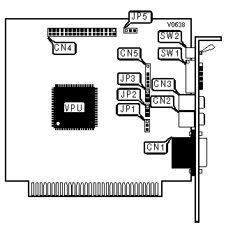
CONNECTIONS | |||
|
Purpose |
Location |
Purpose |
Location |
|
15-pin analog video connector |
CN1 |
VGA feature connector |
CN4 |
|
RCA Video connector 1 |
CN2 |
Light pen connector |
CN5 |
|
RCA Video connector 2 |
CN3 | ||
|
PRIMARY ADAPTER SELECT | ||||
|
Monitor |
SW1/1 |
SW1/2 |
SW1/3 |
SW1/4 |
|
Monochrome Display |
Off |
Off |
On |
Off |
|
Color display/EGA (40 x 25) |
On |
Off |
Off |
On |
|
Color display/EGA (80 x 25) |
Off |
Off |
Off |
On |
|
EGA standard |
On |
On |
On |
Off |
|
EGA enhanced |
Off |
On |
On |
Off |
|
SECONDARY MONOCHROME DISPLAY SELECT | ||||
|
Secondary Monitor |
SW1/1 |
SW1/2 |
SW1/3 |
SW1/4 |
|
CGA/EGA (40 x 25) |
On |
Off |
Off |
On |
|
CGA/EGA (80 x 25) |
Off |
Off |
Off |
On |
|
EGA standard |
On |
On |
On |
Off |
|
EGA Enhanced |
Off |
On |
On |
Off |
|
Note: This setup is with the VEGA Deluxe board as primary and a MDA adapter as secondary. | ||||
|
VEGA AS SECONDARY DISPLAY SELECT | ||||
|
Monitor Type |
SW1/1 |
SW1/2 |
SW1/3 |
SW1/4 |
|
CGA/EGA (40 x 25) |
On |
On |
On |
On |
|
CGA/EGA (80 x 25) |
Off |
On |
On |
On |
|
EGA standard |
On |
Off |
On |
On |
|
EGA Enhanced |
Off |
Off |
On |
On |
|
Note: This setup is with the MDA adapter as primary monitor and VEGA as secondary. | ||||
|
VEGA/CGA DISPLAY CONFIGURATION | ||||
|
Monitor Type |
SW1/1 |
SW1/2 |
SW1/3 |
SW1/4 |
|
CGA mode (40 x 25) |
On |
On |
Off |
On |
|
CGA mode (80 x 25) |
Off |
On |
Off |
On |
|
Note: This setup is with the VEGA adapter as primary monitor and CGA as secondary. | ||||
|
CGA/VEGA DISPLAY CONFIGURATION | ||||
|
Monitor Type |
SW1/1 |
SW1/2 |
SW1/3 |
SW1/4 |
|
CGA mode (40 x 25) |
On |
Off |
On |
Off |
|
CGA mode (80 x 25) |
Off |
Off |
On |
Off |
|
Note: This setup is with the CGA adapter as primary monitor and VEGA as secondary. | ||||
|
DELUXE EMULATION CONFIGURATION | |
|
Monitor Type |
SW1/5 |
|
VEGA Deluxe functions enable |
On |
|
VEGA Deluxe functions disable |
Off |
|
FACTORY CONFIGURED SETTING | |
|
Setting |
JP1 |
|
Do not alter |
N/A |
|
SLOT 8 SETTING | |
|
Setting |
JP2 |
|
Enable |
Pins 1 & 2 closed |
|
Disable |
Pins 2 & 3 closed |
|
Note:Slot 8 on the IBM XT had a different timing than the other 7 slots, this board provides for the option of changing it nature to fit this difference. | |
|
ADDRESS RANGE SETTING | |
|
Address |
JP3 |
|
Enable address in the 2XX range |
Pins 1 & 2 closed |
|
Enable address in the 2XX/3XX range |
Pins 2 & 3 closed |
|
FEATURE CONNECTOR CLOCK SETTING | |
|
Setting |
JP5 |
|
Enable |
Pins 2 & 3 closed |
|
Disable |
Pins 1 & 2 closed |
|
MONITOR TOGGLE SETTING | |
|
Setting |
SW2 |
|
EGA |
To the Right |
|
CGA or Mono |
To the Left |