QUADRANT COMPONENTS, INC.
CHOICE 33.6
|
Card Type |
Modem (asynchronous) |
|
Chipset |
U.S. Robotics |
|
Maximum Data Rate |
33.6Kbps |
|
Maximum Fax Rate |
14.4Kbps |
|
Data Modulation |
Bell 103A, 212A ITU-T V.21, V.22, V.22bis, V.23, V.32, V.32bis, V.34 |
|
Fax Modulation |
Unidentified |
|
Error Correction/Compression |
MNP5, V.42, V.42bis |
|
Fax Class |
Class I & II |
|
Data Bus |
8-bit ISA |
|
Card Size |
Full height, half length |
|
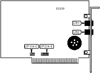
CONNECTIONS | |||
|
Function |
Label |
Function |
Label |
|
Telephone line |
CN1 |
Telephone line |
CN2 |
|
SERIAL PORT ADDRESS SELECTION | |||
|
Setting |
JP1/A |
JP1/B |
JP1/C |
|
3F8h (COM1:) |
Closed |
Closed |
Closed |
|
2F8h (COM2:) |
Open |
Closed |
Closed |
|
3E8h (COM3:) |
Closed |
Open |
Closed |
|
2E8h (COM4:) |
Open |
Open |
Closed |
|
í Plug-N-Play |
Open |
Open |
Open |
|
INTERRUPT SELECTION | |||||
|
Setting |
JP2/A |
JP2/B |
JP2/C |
JP2/D |
JP2/E |
|
2 |
Closed |
Open |
Open |
Open |
Open |
|
3 |
Open |
Closed |
Open |
Open |
Open |
|
4 |
Open |
Open |
Closed |
Open |
Open |
|
5 |
Open |
Open |
Open |
Closed |
Open |
|
7 |
Open |
Open |
Open |
Open |
Closed |
|
í Plug-N-Play |
Open |
Open |
Open |
Open |
Open |
|
SUPPORTED STANDARD COMMANDS |
|
Basic AT Commands |
|
+++, ‘comma’, A/ |
|
A, B, C, D, E, F, H, L, M, O, P, T, V, X |
|
&C, &D, &G, &P, &R, &S, &T, &W, &Z |
|
S-Registers |
|
S0, S1, S2, S3, S4, S5, S6, S7, S8, S9, S10, S11, S12, S18, S25, S38 |
Note: See MHI help file for complete information. |
Proprietary AT Command Set
|
BIT-MAPPED REGISTER S13 | ||
|
Format |
AT [cmds] S13=n [cmds] | |
|
Default: |
0 | |
|
Range: |
0 - 159 | |
|
Description: |
Controls DTR reset, non-error-correcting mode buffer, BS/DEL switch, DTR dialing, reset dialing, and escape sequence reaction. | |
|
Bit |
Value |
Function |
|
0 |
í 01 |
DTR normal. Reset on low DTR. |
|
1 |
í 01 |
Non-error-correcting mode transmit buffer set to 1.5KB. Non-error-correcting mode transmit buffer set to 128 bytes. |
|
2 |
í 01 |
Backspace and delete keys normal. Backspace and delete keys reversed. |
|
3 |
í 01 |
DTR dialing disabled. DTR dialing enabled. |
|
4 |
í 01 |
Reset dialing disabled. Reset dialing enabled. |
|
6, 5 |
00 |
Not used. |
|
7 |
í 01 |
Modem reacts normally to escape sequence. Modem disconnects and returns to command state upon receiving an escape sequence. |
|
BIT-MAPPED REGISTER S27 | ||
|
Format: |
AT [cmds] S27=n [cmds] | |
|
Default: |
0 | |
|
Range: |
0 - 191 | |
|
Description: |
Controls V.21, V.32 encoding and modulation, V.42 answer tone, V.32 fallback, V.32bis mode, and 9600 result codes. | |
|
Bit |
Value |
Function |
|
0 |
í 01 |
V.21 disabled. V.21 enabled. |
|
1 |
í 01 |
V.32 trellis coding disabled. V.32 trellis coding enabled. |
|
2 |
í 01 |
V.32 modulation enabled. V.32 modulation disabled. |
|
3 |
í 01 |
2100Hz answer tone enabled. 2100Hz answer tone disabled. |
|
4 |
í 01 |
V.32 fallback disabled. V.32 fallback enabled. |
|
5 |
í 01 |
V.32bis enabled. V.32bis disabled. |
|
6 |
0 |
Not used. |
|
7 |
í 01 |
Actual result codes displayed. Force 9600 result codes. |
|
BREAK LENGTH | |
|
Type: |
Register |
|
Format: |
AT [cmds] S21=n [cmds] |
|
Default: |
10 |
|
Range: |
Unidentified |
|
Unit: |
10 ms |
|
Description: |
Sets the length of error control mode breaks sent from DCE to DTE. |
|
BREAK TYPE | |
|
Type: |
Configuration |
|
Format: |
AT [cmds] &Yn [cmds] |
|
Description: |
Configures action of break signal. |
|
Command |
Function |
|
&Y0 |
Break empties buffer. |
|
í &Y1 |
Break empties buffer and is sent immediately. |
|
&Y2 |
Break does not empty buffer and is sent immediately. |
|
COMMUNICATIONS MODE | |
|
Type: |
Configuration |
|
Format: |
AT [cmds] &Mn [cmds] |
|
Description: |
Selects communications mode. |
|
Command |
Mode |
|
í &M0 |
Modem operates in asynchronous mode. |
|
&M5 |
Modem operates in asynchronous auto-reliable mode. |
|
&M6 |
Modem operates in asynchronous reliable mode. |
|
COMPRESSION MODE | |
|
Type: |
Configuration |
|
Format: |
AT [cmds] &Kn [cmds] |
|
Description: |
Selects the type of data compression that will be used. |
|
Command |
Function |
|
&K0 |
Data compression disabled. |
|
í &K1 |
Auto-detect compression mode. |
|
&K2 |
Data compression enabled. |
|
&K3 |
MNP5 data compression only enabled. |
|
CONNECTION SPEED LOWER LIMIT | |
|
Type: |
Configuration |
|
Format: |
AT [cmds] &Un [cmds] |
|
Description: |
Sets slowest allowed connection speed if &N is set to 1 or higher. |
|
Command |
Function |
|
&U0 |
No minimum connect speed. |
|
&U1 |
Set minimum connect speed to 300bps. |
|
&U2 |
Set minimum connect speed to 1200bps. |
|
&U3 |
Set minimum connect speed to 2400bps. |
|
&U4 |
Set minimum connect speed to 4800bps. |
|
&U5 |
Set minimum connect speed to 7200bps. |
|
&U6 |
Set minimum connect speed to 9600bps. |
|
&U7 |
Set minimum connect speed to 12Kbps. |
|
&U8 |
Set minimum connect speed to 14.4Kbps. |
|
&U9 |
Set minimum connect speed to 16.8Kbps. |
|
&U10 |
Set minimum connect speed to 19.2Kbps. |
|
&U11 |
Set minimum connect speed to 21.6Kbps. |
|
&U12 |
Set minimum connect speed to 24Kbps. |
|
&U13 |
Set minimum connect speed to 26.4Kbps. |
|
&U14 |
Set minimum connect speed to 28.8Kbps. |
|
&U15 |
Set minimum connect speed to 31.2Kbps. |
|
&U16 |
Set minimum connect speed to 33.6Kbps. |
|
CONNECTION SPEED UPPER LIMIT | |
|
Type: |
Configuration |
|
Format: |
AT [cmds] &Nn [cmds] |
|
Description: |
Sets required connection speed if &U is set to 0; otherwise, sets fastest allowed connection speed. |
|
Command |
Function |
|
&N0 |
No maximum connect speed. |
|
&N1 |
Set maximum connect speed to 300bps. |
|
&N2 |
Set maximum connect speed to 1200bps. |
|
&N3 |
Set maximum connect speed to 2400bps. |
|
&N4 |
Set maximum connect speed to 4800bps. |
|
&N5 |
Set maximum connect speed to 7200bps. |
|
&N6 |
Set maximum connect speed to 9600bps. |
|
&N7 |
Set maximum connect speed to 12Kbps. |
|
&N8 |
Set maximum connect speed to 14.4Kbps. |
|
&N9 |
Set maximum connect speed to 16.8Kbps. |
|
&N10 |
Set maximum connect speed to 19.2Kbps. |
|
&N11 |
Set maximum connect speed to 21.6Kbps. |
|
&N12 |
Set maximum connect speed to 24Kbps. |
|
&N13 |
Set maximum connect speed to 26.4Kbps. |
|
&N14 |
Set maximum connect speed to 28.8Kbps. |
|
&N15 |
Set maximum connect speed to 31.2Kbps. |
|
&N16 |
Set maximum connect speed to 33.6Kbps. |
|
DISPLAY INFORMATION | |
|
Type: |
Immediate |
|
Format: |
AT [cmds] In [cmds] |
|
Description: |
Displays information requested about the modem. |
|
Command |
Function |
|
I0 |
Displays product code. |
|
I1 |
Displays ROM checksum result. |
|
I2 |
Displays RAM checksum result. |
|
I3 |
Displays firmware version. |
|
I4 |
Displays current command settings. |
|
I5 |
Displays current NVRAM settings. |
|
I6 |
Displays link diagnostics. |
|
I7 |
Displays configuration. |
|
I9 |
Displays Plug-N-Play information. |
|
I11 |
Displays call statistics. |
|
ERROR CORRECTION/COMPRESSION | ||
|
Format: |
AT [cmds] S15=n [cmds] | |
|
Default: |
0 | |
|
Range: |
0 - 255 | |
|
Description: |
Selects which classes of error correction and compression may be used. | |
|
Bit |
Value |
Function |
|
0 |
í 01 |
MNP and V.42 enabled during V.22 operation. MNP and V.42 disabled during V.22 operation. |
|
1 |
í 01 |
MNP and V.42 enabled during V.22bis operation. MNP and V.42 disabled during V.22bis operation. |
|
2 |
í 01 |
MNP and V.42 enabled during V.32 and V.32bis operation. MNP and V.42 disabled during V.32 and V.32bis operation. |
|
3 |
í 01 |
MNP enabled. MNP disabled. |
|
4 |
í 01 |
MNP 4 enabled. MNP 4 disabled. |
|
5 |
í 01 |
MNP 3 enabled. MNP 3 disabled. |
|
6 |
í 01 |
MNP normal. MNP adjusted for non compliant modems. |
|
7 |
í 01 |
V.42 enabled. V.42 disabled. |
|
EXTENDED RESULT CODES | |
|
Type: |
Configuration |
|
Format: |
AT [cmds] &An [cmds] |
|
Description: |
Selects extended result codes. |
|
Command |
Function |
|
&A0 |
Extended result codes disabled. |
|
&A1 |
ARQ result codes enabled. |
|
&A2 |
V.32 result code enabled. |
|
&A3 |
Error control and compression result codes enabled. |
|
FACTORY DEFAULTS | |
|
Type: |
Immediate |
|
Format: |
AT [cmds] &Fn [cmds] |
|
Description: |
Resets the modem to the specified factory profile. |
|
Command |
Function |
|
&F0 |
Modem resets to factory generic profile. |
|
&F1 |
Modem resets to factory hardware flow control profile. |
|
&F2 |
Modem resets to factory software flow control profile. |
|
FLOW CONTROL CHARACTER - XON | |
|
Type: |
Register |
|
Format: |
AT [cmds] S22=n [cmds] |
|
Default: |
17 |
|
Range: |
11 - 127 |
|
Unit: |
ASCII |
|
Description: |
Sets the character used to represent XON. |
|
FLOW CONTROL CHARACTER - XOFF | |
|
Type: |
Register |
|
Format: |
AT [cmds] S23=n [cmds] |
|
Default: |
19 |
|
Range: |
11 - 127 |
|
Unit: |
ASCII |
|
Description: |
Sets the character used to represent XOFF. |
|
FLOW CONTROL TYPE | |
|
Type: |
Configuration |
|
Format: |
AT [cmds] &Hn [cmds] |
|
Description: |
Sets type of flow control used by modem. |
|
Command |
Function |
|
&H0 |
Flow control disabled. |
|
&H1 |
CTS/RTS flow control enabled. |
|
&H2 |
XON/XOFF flow control enabled. |
|
&H3 |
CTS/RTS and XON/XOFF flow control enabled. |
|
HELP - AMPERSAND | |
|
Type: |
Immediate |
|
Format: |
AT [cmds] &$ |
|
Description: |
Displays help on the AT& commands. |
|
HELP - DIAL | |
|
Type: |
Immediate |
|
Format: |
AT [cmds] D$ |
|
Description: |
Displays help on dial modifiers. |
|
HELP - GENERAL | |
|
Type: |
Immediate |
|
Format: |
AT [cmds] $ |
|
Description: |
Displays help on the basic (no prefix) AT commands. |
|
HELP - S-REGISTERS | |
|
Type: |
Immediate |
|
Format: |
AT [cmds] S$ |
|
Description: |
Displays help on the S-registers. |
|
INACTIVITY TIMER | |
|
Type: |
Register |
|
Format: |
AT [cmds] S19=n [cmds] |
|
Default: |
0 |
|
Range: |
0-255 |
|
Unit: |
1 minute |
|
Description: |
Sets the length of time that the modem does not receive information before it disconnects; S19=0 will disable this function. |
|
LOCK SERIAL PORT | |
|
Type: |
Configuration |
|
Format: |
AT [cmds] &Bn [cmds] |
|
Description: |
Sets operation of serial port speed. |
|
Command |
Function |
|
&B0 |
Serial speed follows connect speed. |
|
&B1 |
Serial speed locked. |
|
&B2 |
Serial speed locked in ARQ mode only. |
|
PROFILE ON POWER-UP | |
|
Type: |
Configuration |
|
Format: |
AT [cmds] Yn [cmds] |
|
Description: |
Selects the profile that the modem will reset to on power-up. |
|
Command |
Function |
|
í Y0 |
Modem resets to user profile 0 on power-up. |
|
Y1 |
Modem resets to user profile 1 on power-up. |
|
Y2 |
Modem resets to factory generic profile on power-up. |
|
Y3 |
Modem resets to factory hardware flow control profile on power-up. |
|
Y4 |
Modem resets to factory software flow control profile on power-up. |
|
RESET MODEM | |
|
Type: |
Immediate |
|
Format: |
AT [cmds] Zn [cmds] |
|
Description: |
Resets the modem to the specified profile. |
|
Command |
Function |
|
Z0 |
Modem resets to profile set with the Y command. |
|
Z1 |
Modem resets to user profile 0. |
|
Z2 |
Modem resets to user profile 1. |
|
Z3 |
Modem resets to factory generic profile. |
|
Z4 |
Modem resets to factory hardware flow control profile. |
|
Z5 |
Modem resets to factory software flow control profile. |
|
RESULT CODES | |
|
Type: |
Configuration |
|
Format: |
AT [cmds] Qn [cmds] |
|
Description: |
Enables modem to send result codes to the DTE. |
|
Command |
Function |
|
í Q0 |
Result codes enabled. |
|
Q1 |
Result codes disabled. |
|
Q2 |
Result codes enabled in originate mode only. |
|
TONE DIALING TEST | |
|
Type: |
Register |
|
Format: |
AT [cmds] S16=n [cmds] |
|
Description: |
Begins a tone dialing test. |
|
Command |
Function |
|
í S16=0 |
Tone dialing test disabled. |
|
S16=2 |
Tone dialing test enabled. |
|
V.21 ANSWER MODE FALLBACK TIMER | |
|
Type: |
Register |
|
Format: |
AT [cmds] S29=n [cmds] |
|
Default: |
20 |
|
Range: |
Unidentified |
|
Unit: |
.1 second |
|
Description: |
The function of this register is unidentified. |
|
V.32 HANDSHAKE TIME | |
|
Type: |
Register |
|
Format: |
AT [cmds] S28=n [cmds] |
|
Default: |
8 |
|
Range: |
0 - 255 |
|
Unit: |
.1 second |
|
Description: |
Sets length of V.32 handshake. Setting S28 to 255 disables all connections except 9600bps V.32 mode. |
|
V.34 AND V.FC OPTIONS | |||||
|
Format: |
AT [cmds] S32=n [cmds] | ||||
|
Default: |
2 | ||||
|
Range: |
0 - 31 | ||||
|
Description: |
Controls various V.34 and V.FC options. | ||||
|
Bit |
Value |
Function | |||
|
0 |
í 01 |
Call indicate during V.34 operation disabled. Call indicate during V.34 operation enabled. | |||
|
1 |
0 í 1 |
V.8 during V.34 operation disabled. V.8 during V.34 operation enabled. | |||
|
2 |
í 01 |
V.FC modulation enabled. V.FC modulation disabled. | |||
|
3 |
í 01 |
V.34 modulation enabled. V.34 modulation disabled. | |||
|
4 |
í 01 |
33.6Kbps V.34 modulation enabled. 33.6Kbps V.34 modulation disabled. | |||
|
V.34 OPTIONS | ||
|
Format: |
AT [cmds] S33=n [cmds] | |
|
Default: |
0 | |
|
Range: |
0 - 191 | |
|
Description: |
Controls V.34 baud rate and shaping. | |
|
Bit |
Value |
Function |
|
0 |
í 01 |
2400 baud rate enabled. 2400 baud rate disabled. |
|
1 |
í 01 |
2743 baud rate enabled. 2743 baud rate disabled. |
|
2 |
í 01 |
2800 baud rate enabled. 2800 baud rate disabled. |
|
3 |
í 01 |
3000 baud rate enabled. 3000 baud rate disabled. |
|
4 |
í 01 |
3200 baud rate enabled. 3200 baud rate disabled. |
|
5 |
í 01 |
3429 baud rate enabled. 3429 baud rate disabled. |
|
6 |
0 |
Not used. |
|
7 |
í 01 |
Shaping enabled. Shaping disabled. |
|
V.34 OPTIONS | ||
|
Format: |
AT [cmds] S34=n [cmds] | |
|
Default: |
0 | |
|
Range: |
0 - 255 | |
|
Description: |
Controls V.34 mapping, non-linear coding, transmit level deviation, pre-emphasis, and pre-coding. | |
|
Bit |
Value |
Function |
|
0 |
í 01 |
8S-2D map enabled. 8S-2D map disabled. |
|
1 |
í 01 |
16S-4D map enabled. 16S-4D map disabled. |
|
2 |
í 01 |
32S-2D map enabled. 32S-2D map disabled. |
|
3 |
í 01 |
64S-4D map enabled. 64S-4D map disabled. |
|
4 |
í 01 |
Non-linear coding enabled. Non-linear coding disabled. |
|
5 |
í 01 |
Transmit level deviation enabled. Transmit level deviation disabled. |
|
6 |
í 01 |
Pre-emphasis enabled. Pre-emphasis disabled. |
|
7 |
í 01 |
Pre-coding enabled. Pre-coding disabled. |
|
XON/XOFF PASS-THROUGH | |
|
Type: |
Configuration |
|
Format: |
AT [cmds] &In [cmds] |
|
Description: |
Selects whether XON/XOFF signals are sent to remote modem. |
|
Command |
Function |
|
&I0 |
Software flow control disabled. |
|
&I1 |
XON/XOFF pass-through enabled. |
|
&I2 |
XON/XOFF pass-through disabled. |