POWERCOM AMERICA, INC.
2814 EXTERNAL
|
Card Type |
Fax, Modem (synchronous/asynchronous) |
|
Chip Set |
Unidentified |
|
Maximum Data Rate |
28.8Kbps |
|
Maximum Fax Rate |
14.4Kbps |
|
Data Bus |
External |
|
Fax Class |
Class I |
|
Data Modulation Protocol |
Bell 103/212A ITU-T V.21, V.22, V.22bis, V.23, V.32, V.32bis, V.34 |
|
Fax Modulation Protocol |
ITU-T V.17, V.21CH2, V.27ter, V.29 |
|
Error Correction/Compression |
MNP5, V.42bis |
|
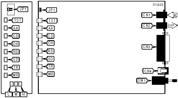
CONNECTIONS | ||||||
|
Function |
Label |
Function |
Label | |||
|
Line in |
CN1 |
DC power |
CN4 | |||
|
Line out |
CN2 |
Power switch |
SW1 | |||
|
RS-232/422 |
CN3 | |||||
|
USER CONFIGURABLE SETTINGS | ||
|
Function |
Label |
Position |
|
í SMART mode |
JP1 |
Open |
|
DUMB mode |
JP1 |
Closed |
|
DIAGNOSTIC LED(S) | ||||||
|
LED |
Color |
Status |
Condition | |||
|
TST |
Red |
Blinking |
Errors detected and error correction activated | |||
|
TST |
Red |
Off |
No errors detected | |||
|
AA |
Red |
On |
Auto-answer enabled | |||
|
AA |
Red |
Off |
Auto-answer disabled | |||
|
AA |
Red |
Blinking |
Phone is ringing | |||
|
CD |
Red |
On |
Carrier signal detected | |||
|
CD |
Red |
Off |
Carrier signal not detected | |||
|
CD |
Red |
Blinking |
Modem is retraining | |||
|
OH |
Red |
On |
Modem is off-hook | |||
|
OH |
Red |
Off |
Modem is on-hook | |||
|
RD |
Red |
On |
Modem is receiving data | |||
|
RD |
Red |
Off |
Modem is not receiving data | |||
|
SD |
Red |
On |
Modem is transmitting data | |||
|
SD |
Red |
Off |
Modem is not transmitting data | |||
|
TR |
Red |
On |
DTR signal is high | |||
|
TR |
Red |
Off |
DTR signal is low | |||
|
MR |
Red |
On |
Power is on | |||
|
MR |
Red |
Off |
Power is off | |||
|
MR |
Red |
Blinking |
Modem in self-test mode | |||
|
H Status |
M Status |
L Status |
Condition | |||
|
Green |
Green |
Green |
Modem operating at 28.8Kbps | |||
|
Green |
Green |
Off |
Modem operating at 26.4Kbps | |||
|
Green |
Off |
Green |
Modem operating at 24Kbps | |||
|
Green |
Off |
Off |
Modem operating at 21.6Kbps | |||
|
Off |
Green |
Green |
Modem operating at 19.2Kbps | |||
|
Off |
Green |
Off |
Modem operating at 16.8Kbps | |||
|
Red |
Red |
Red |
Modem operating at 14.4Kbps | |||
|
Red |
Red |
Off |
Modem operating at 12Kbps | |||
|
Red |
Off |
Red |
Modem operating at 9600bps | |||
|
Red |
Off |
Off |
Modem operating at 7200bps | |||
|
Off |
Red |
Red |
Modem operating at 4800bps | |||
|
Off |
Red |
Off |
Modem operating at 2400bps | |||
|
Off |
Off |
Red |
Modem operating at 1200bps | |||
|
Off |
Off |
Off |
Modem operating at 300bps | |||
Proprietary AT Command Set
|
AUTO-RELIABLE FALLBACK CHARACTER | |
|
Type: |
Configuration |
|
Format: |
AT [cmds] %An [cmds] |
|
Default: |
19 |
|
Range: |
0-127 |
|
Unit: |
ASCII |
|
Description: |
Sets the character used as the auto-reliable fallback character; %A0 will disable this function. |
|
AUTO-RELIABLE TIME BUFFER CONFIGURATION | |
|
Type: |
Configuration |
|
Format: |
AT [cmds] \Cn [cmds] |
|
Description: |
Controls the handling of incoming data during auto-reliable time period |
|
Command |
Function |
|
í \C0 |
Data is discarded |
|
\C1 |
Data is buffered |
|
\C2 |
Data is discarded; modem returns to normal mode on receiving auto-reliable fallback character. |
|
AUTOMATIC POWER LEVEL ADJUSTMENT | |
|
Type: |
Configuration |
|
Format: |
AT [cmds] %Pn [cmds] |
|
Description: |
Controls automatic transmit power level adjustment during leased-line mode |
|
Command |
Function |
|
í %P0 |
Automatic power level adjustment disabled |
|
%P1 |
Automatic power level adjustment enabled |
|
BIT-MAPPED REGISTER S14 | ||
|
Format: |
AT [cmds] S14=n [cmds] | |
|
Default: |
138 | |
|
Range: |
0-255 | |
|
Unit: |
Bit-mapped | |
|
Description: |
Controls echo, result codes and display, dial mode, smart/dumb mode, restore profile on power-up, and answer/originate mode. | |
|
Bit |
Value |
Function |
|
0 |
í 01 |
V.42 extended result code disabled V.42 extended result code enabled |
|
1 |
0 í 1 |
Command echo disabled Command echo enabled |
|
2 |
í 01 |
Result codes enabled Result codes disabled |
|
3 |
0 í 1 |
Display result codes in numeric format Display result codes in verbose format |
|
4 |
í 01 |
SMART mode DUMB mode |
|
5 |
í 01 |
Tone dial enabled Pulse dial enabled |
|
6 |
í 01 |
Restore profile 0 on power-up Restore profile 1 on power-up |
|
7 |
0 í 1 |
Answer mode enabled Originate mode enabled |
|
BIT-MAPPED REGISTER S21 | ||
|
Format |
AT [cmds] S21=n [cmds] | |
|
Default: |
48 | |
|
Range: |
0-254 | |
|
Unit: |
Bit-mapped | |
|
Description: |
Selects line type, CTS/DCD/DSR signals, low DTR action, and the long space disconnect function. | |
|
Bit |
Value |
Function |
|
0 |
0 |
Not used |
|
1 |
í 01 |
Switched line Leased-line |
|
2 |
í 01 |
CTS follows RTS CTS forced high |
|
4, 3 |
00 01 í 1011 |
DTR signal ignored Modem goes to command mode on low DTR Modem disconnects on low DTR; Auto-Answer is disabled. Modem is initialized on low DTR |
|
5 |
0 í 1 |
DCD forced high DCD normal |
|
6 |
í 01 |
DSR forced high DSR normal |
|
7 |
í 01 |
Long space disconnect function disabled Long space disconnect function enabled |
|
BIT-MAPPED REGISTER S22 | ||
|
Format |
AT [cmds] S22=n [cmds] | |
|
Default: |
118 | |
|
Range: |
0-127 | |
|
Unit: |
Bit-mapped | |
|
Description: |
Controls speaker volume and controls, and limits results codes. | |
|
Bit |
Value |
Function |
|
1, 0 |
00 01 í 1011 |
Low level volume Low level volume Medium level volume High level volume |
|
3, 2 |
00 í 0110 11 |
Speaker off Speaker off on carrier Speaker always on Speaker on during handshake |
|
6 - 4 |
000 100 101 110 í 111 |
Basic result codes only enabled Basic and connection speed result codes enabled Basic and connection speed result codes and dialtone detection enabled All result codes except dialtone detection enabled All result codes enabled |
|
BIT-MAPPED REGISTER S23 | ||
|
Format |
AT [cmds] S23=n [cmds] | |
|
Default: |
Unidentified | |
|
Range: |
0-60 | |
|
Unit: |
Bit-mapped | |
|
Description: |
Controls DTE rate and parity. | |
|
Bit |
Value |
Function |
|
3 - 0 |
0000 0001 0010 0011 0100 0101 0110 0111 1000 1001 1010 1011 1100 |
Sets serial port speed to 110bps Sets serial port speed to 300bps Sets serial port speed to 600bps Sets serial port speed to 1200bps Sets serial port speed to 2400bps Sets serial port speed to 4800bps Sets serial port speed to 9600bps Sets serial port speed to 14400bps Sets serial port speed to 19200bps Sets serial port speed to 38400bps Sets serial port speed to 56700bps Sets serial port speed to 76800bps Sets serial port speed to 115200bps |
|
5, 4 |
í 0001 10 11 |
Parity even Space Parity Parity odd Mark or No Parity |
|
BIT-MAPPED REGISTER S27 | ||
|
Format |
AT [cmds] S27=n [cmds] | |
|
Default: |
5 | |
|
Range: |
0-165 | |
|
Unit: |
Bit-mapped | |
|
Description: |
Selects synchronous/asynchronous mode, line type, clock source, and ITU-T/Bell modes. | |
|
Bit |
Value |
Function |
|
2 - 0 |
000 001 010 011 í 101 |
Asynchronous mode Asynchronous off-line command mode then synchronous connect mode Synchronous terminal support Synchronous connect mode on originating a call Error correction mode |
|
3 |
í 0 |
Not used |
|
5, 4 |
í 0001 10 |
Local modem generates transmit clock source Local DTE generates transmit clock source Remote DCE/DTE generates transmit clock source |
|
6, 7 |
í 0001 10 |
ITU/T mode Bell mode ITU/T V.23 at 1200bps (not used on US versions) |
|
BIT-MAPPED REGISTER S28 | ||
|
Format |
AT [cmds] S28=n [cmds] | |
|
Default: |
Unidentified | |
|
Range: |
0-27 | |
|
Unit: |
Bit-mapped | |
|
Description: |
Controls automatic power level adjustment and line speed. | |
|
Bit |
Value |
Function |
|
0 |
í 01 |
Automatic power level adjustment disabled Automatic power level adjustment enabled |
|
4 - 1 |
0000 0001 0010 0011 0100 0101 0110 0111 1000 1001 1010 1011 1100 1101 |
Set line speed to 300bps Set line speed to 1200bps Set line speed to 2400bps Set line speed to 4800bps Set line speed to 7200bps Set line speed to 9600bps Set line speed to 12Kbps Set line speed to 14.4Kbps Set line speed to 16.8Kbps Set line speed to 19.2Kbps Set line speed to 21.6Kbps Set line speed to 24Kbps Set line speed to 26.4Kbps Set line speed to 28.8Kbps |
|
BIT-MAPPED REGISTER S40 | |||||
|
Format: |
AT [cmds] S40=n [cmds] | ||||
|
Default: |
3 | ||||
|
Range: |
0-3 | ||||
|
Description: |
Sets the maximum transmittable block size | ||||
|
Bit |
Value |
Function | |||
|
1, 0 |
00 01 10 í 11 |
MNP block size is 64 characters MNP block size is 128 characters MNP block size is 192 characters MNP block size is 256 characters | |||
|
BIT-MAPPED REGISTER S41 | |||||
|
Format: |
AT [cmds] S41=n [cmds] | ||||
|
Default: |
0 | ||||
|
Range: |
0-1 | ||||
|
Description: |
Selects data compression | ||||
|
Bit |
Value |
Function | |||
|
0 |
í 01 |
Data compression disabled MNP5 enabled | |||
|
BREAK SEND | |
|
Type: |
Configuration |
|
Format: |
AT [cmds] \Bn [cmds] |
|
Default: |
3 |
|
Range: |
1-9 |
|
Unit: |
.1 second |
|
Description: |
Sends break to modem |
|
COMMUNICATIONS MODE | |
|
Type: |
Configuration |
|
Format: |
AT [cmds] &Qn [cmds] |
|
Description: |
Selects communications mode options |
|
Command |
Mode |
|
&Q0 |
Asynchronous mode |
|
&Q1 |
Asynchronous off-line command mode then synchronous connect mode |
|
&Q2 |
Synchronous terminal support |
|
&Q3 |
Synchronous connect mode on originating a call |
|
í &Q5 |
Error correction mode |
|
COMPRESSION | |
|
Type: |
Configuration |
|
Format: |
AT [cmds] %Cn [cmds] |
|
Description: |
Selects data compression |
|
Command |
Function |
|
í %C0 |
Data compression disabled |
|
%C1 |
MNP5 enabled |
|
CONNECT MODE | |
|
Type: |
Configuration |
|
Format: |
AT [cmds] \Nn [cmds] |
|
Description: |
Controls the type of connection the modem will operate in |
|
Command |
Function |
|
\N0 |
Normal mode enabled |
|
í \N1 |
Direct mode enabled |
|
\N2 |
MNP reliable mode enabled |
|
\N3 |
Auto-reliable mode enabled |
|
DATA SET READY (DSR) | |
|
Type: |
Configuration |
|
Format: |
AT [cmds] &Sn [cmds] |
|
Description: |
Selects DSR options |
|
Command |
Function |
|
í &S0 |
DSR forced high |
|
&S1 |
DSR high only while modem is handshaking or connected |
|
LOCK SERIAL PORT | |
|
Type: |
Configuration |
|
Format: |
AT [cmds] \Jn [cmds] |
|
Description: |
Sets operation of serial port speed |
|
Command |
Function |
|
\J0 |
Serial speed locked |
|
í \J1 |
Serial speed follows connect speed |
|
EXTENDED RESULT CODES | |
|
Type: |
Configuration |
|
Format: |
AT [cmds] \Vn [cmds] |
|
Description: |
Selects MNP extended result codes |
|
Command |
Function |
|
í \V0 |
MNP extended result codes disabled |
|
\V1 |
MNP extended result codes enabled |
|
FLOW CONTROL TYPE | |
|
Type: |
Configuration |
|
Format: |
AT [cmds] \Qn [cmds] |
|
Description: |
Sets type of flow control used by modem |
|
Command |
Function |
|
\Q0 |
Flow control disabled |
|
\Q1 |
XON/XOFF flow control enabled |
|
í \Q2 |
CTS flow control by DCE enabled |
|
\Q3 |
Bidirectional RTS/CTS flow control enabled |
|
INACTIVITY TIMER | |
|
Type: |
Configuration |
|
Format: |
AT [cmds] \Tn [cmds] |
|
Default: |
0 |
|
Range: |
0-90 |
|
Unit: |
1 second |
|
Description: |
Sets the length of time that the modem does not receive information before it disconnects. |
|
INACTIVITY TIMER | |
|
Type: |
Register |
|
Format: |
AT [cmds] S39=n [cmds] |
|
Default: |
0 |
|
Range: |
0-90 |
|
Unit: |
1 second |
|
Description: |
Sets the length of time that the modem does not receive information before it disconnects. |
|
MAXIMUM BLOCK SIZE FOR TRANSMISSION | |
|
Type: |
Configuration |
|
Format: |
AT [cmds] \An [cmds] |
|
Description: |
Sets the maximum transmittable block size |
|
Command |
Function |
|
\A0 |
MNP block size is 64 characters |
|
\A1 |
MNP block size is 128 characters |
|
\A2 |
MNP block size is 192 characters |
|
í \A3 |
MNP block size is 256 characters |
|
RTS/CTS | |
|
Type: |
Configuration |
|
Format: |
AT [cmds] &Rn [cmds] |
|
Description: |
Selects RTS/CTS options |
|
Command |
Function |
|
í &R0 |
CTS follows RTS |
|
&R1 |
RTS is ignored; CTS forced high. |
|
TEST MODES | ||
|
Type: |
Register | |
|
Format: |
AT [cmds] S16=n [cmds] | |
|
Default: |
0 | |
|
Range: |
0-125 | |
|
Unit: |
Bit-mapped | |
|
Description: |
Controls loopback tests, analog, digital, remote digital, and self tests. | |
|
Bit |
Value |
Function |
|
0 |
í 01 |
Local analog loopback not in progress Local analog loopback in progress |
|
1 |
í 0 |
Not used |
|
2 |
í 01 |
Local digital loopback not in progress Local digital loopback in progress |
|
3 |
í 01 |
Modem not in remote digital loopback Remote digital loopback in progress |
|
4 |
í 01 |
Remote digital loopback not requested Remote digital loopback requested |
|
5 |
í 01 |
Remote digital loopback w/ self-test not in progress Remote digital loopback w/ self-test in progress |
|
6 |
í 01 |
Local analog loopback w/ self-test not in progress Local analog loopback w/ self-test in progress |
|
XON/XOFF PASS-THROUGH | |
|
Type: |
Configuration |
|
Format: |
AT [cmds] \Xn [cmds] |
|
Description: |
Selects whether XON/XOFF signals are sent to remote modem |
|
Command |
Function |
|
\X0 |
XON/XOFF signals trapped by local modem |
|
í \X1 |
XON/XOFF passed through local modem |