RAD DATA COMMUNICATIONS
ASM-20 G.703
|
Modem Type |
Data (Synchronous) |
|
Maximum Data Rate |
64Kbps |
|
Data Bus |
External |
|
Data Modulation Protocol |
Proprietary |

|
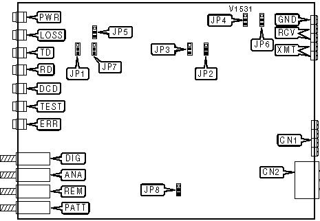
CONNECTIONS | |||
|
Purpose |
Location |
Purpose |
Location |
|
G-703 |
CN1 |
Diagnostic test switch |
DIG |
|
AC power |
CN2 |
Analog loopback switch |
ANA |
|
Ground |
GND |
Remote loopback switch |
REM |
|
Receive |
RCV |
Test pattern |
PATT |
|
Transmit |
XMT | ||
|
CD SIGNAL | |
| Setting |
JP1 |
| CD normal |
Pins 2 & 3 closed |
| » CD forced high |
Pins 1 & 2 closed |
|
CHASSIS TO SIGNAL GROUND | |
| Setting |
JP6 |
| » Connected |
Pins 2 & 3 closed |
| Disconnected |
Pins 1 & 2 closed |
|
ENABLE PUSHBUTTONS | |
| Setting |
JP5 |
| » DIG, ANA, REM, PATT enabled |
Pins 1 & 2 closed |
| Disabled |
Pins 2 & 3 closed |
|
JITTER FILTER | |
| Setting |
JP8 |
| Enabled |
Pins 1 & 2 closed |
| » Disabled |
Pins 2 & 3 closed |
|
RECEIVE IMPEDANCE | |
| Setting |
JP4 |
| » 135omhs |
Pins 1 & 2 closed |
| Low |
Pins 2 & 3 closed |
|
TRANSMIT IMPEDANCE | |
| Setting |
JP3 |
| » 135omhs |
Pins 1 & 2 closed |
| Low |
Pins 2 & 3 closed |
|
TRANSMIT LEVEL | |
| Setting |
JP2 |
| » 0dBm |
Pins 2 & 3 closed |
| -6dBm |
Pins 1 & 2 closed |
|
V.54 DELAY | |
| Setting |
JP7 |
| » On |
Pins 2 & 3 closed |
| Off |
Pins 1 & 2 closed |
|
DIAGNOSTIC LED(S) | |||
|
LED |
Color |
Status |
Condition |
|
PWR |
Green |
On |
Power is on |
|
PWR |
Green |
Off |
Power is off |
|
RTS |
Yellow |
On |
Request to Send enabled |
|
RTS |
Yellow |
Off |
Request to Send disabled |
|
TD |
Yellow |
On |
Modem is transmitting steady SPACE |
|
TD |
Yellow |
Off |
Modem is not transmitting data |
|
TD |
Yellow |
Blinking |
Modem is transmitting data |
|
RD |
Yellow |
On |
Modem is receiving steady SPACE |
|
RD |
Yellow |
Off |
Modem is not receiving data |
|
RD |
Yellow |
Blinking |
Modem is receiving data |
|
DCD |
Yellow |
On |
Carrier signal detected |
|
DCD |
Yellow |
Off |
Carrier signal not detected |
|
TEST |
Red |
On |
Modem in test mode |
|
TEST |
Red |
Off |
Modem not in test mode |
|
ERR |
Yellow |
On |
Errors in test pattern |
|
ERR |
Yellow |
Off |
Good test pattern |