MOTOROLA, INC.
V.32E
|
Card Type |
Modem (synchronous/asynchronous) |
|
Chip Set |
Motorola |
|
Maximum Data Rate |
9600bps |
|
Data Bus |
Serial |
|
Data Modulation Protocol |
Bell 103A/212A ITU-T V.21, V.22, V.22bis, V.23, V.32 |
|
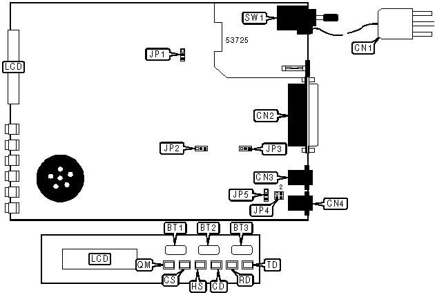
CONNECTIONS | |||
|
Function |
Label |
Function |
Label |
|
YES button |
BT1 |
Line out |
CN3 |
|
NO button |
BT2 |
Line in |
CN4 |
|
Talk/Data button |
BT3 |
LCD display |
LCD |
|
AC power in |
CN1 |
Power switch |
SW1 |
|
Serial port |
CN2 | ||
|
USER CONFIGURABLE SETTINGS | ||
|
Setting |
Label |
Position |
|
í Signal ground connected to chassis ground |
JP1 |
Pins 1 & 2 closed |
|
Signal ground not connected to chassis ground |
JP1 |
Pins 2 & 3 closed |
|
í Quality monitor signal high indicates poor signal quality |
JP2 |
Pins 1 & 2 closed |
|
Quality monitor signal low indicates poor signal quality |
JP2 |
Pins 2 & 3 closed |
|
í Quality Monitor signal connected to CN2 pin 11 |
JP3 |
Pins 1 & 2 closed |
|
Quality Monitor signal not connected |
JP3 |
Pins 2 & 3 closed |
|
í Telephone line polarity normal |
JP4 |
Pins 1 & 2, 3 & 4 closed |
|
Telephone line polarity reversed |
JP4 |
Pins 1 & 3, 2 & 4 closed |
|
í Factory configured - do not alter |
JP5 |
Pins 2 & 3 closed |
|
DIAGNOSTIC LED(S) | |||
|
LED |
Color |
Status |
Condition |
|
TD |
Red |
On |
Modem is transmitting data |
|
TD |
Red |
Off |
Modem is not transmitting data |
|
RD |
Red |
On |
Modem is receiving data |
|
RD |
Red |
Off |
Modem is not receiving data |
|
CD |
Red |
On |
Carrier signal detected |
|
CD |
Red |
Off |
Carrier signal not detected |
|
CS |
Red |
On |
CTS signal is high |
|
CS |
Red |
Off |
CTS signal is low |
|
QM |
Red |
On |
Bit Error Rate exceeds 10 4 |
|
QM |
Red |
Off |
Bit Error Rate is less than 10 4 |
Note: The function of the HS LED is unidentified. | |||
|
SUPPORTED STANDARD COMMANDS |
|
Basic AT Commands |
|
+++, ‘comma’, A/ |
|
A, D, E, H, L, M, O, Q, V, X, Y, Z |
|
&D, &F, &G, &P, &V, &W, &X |
|
Extended AT Commands |
|
%E |
|
S-Registers |
|
S0, S1, S2, S3, S4, S5, S6, S7, S8, S9, S10, S11, S12, S14, S16, S18, S22, S23, S25, S26 |
|
V.25bis Commands |
|
CRN, PRN, CRS |
Note: See MHI documentation for complete information. |
Proprietary AT Command Set
|
ANSWER/ORIGINATE MODE | |
|
Type: |
Configuration |
|
Format: |
AT [cmds] *ORn [cmds] |
|
Description: |
Selects whether the modem is in answer or originate mode. |
|
Command |
Function |
|
í *OR0 |
Modem is in originate mode. |
|
*OR1 |
Modem is in answer mode. |
|
BIT-MAPPED REGISTER S32 | ||
|
Format |
AT [cmds] S32=n [cmds] | |
|
Default: |
6 | |
|
Range: |
0 - 15 | |
|
Description: |
Controls line type, disconnect on loss of current, and leased line backup mode. | |
|
Bit |
Value |
Function |
|
0 |
í 01 |
2-wire leased line. 4-wire leased line. |
|
2, 1 |
00 10 í 11 |
Do not disconnect on loss of current. Disconnect after 8ms if current is lost. Disconnect after 90ms if current is lost. |
|
3 |
í 01 |
Modem will reestablish a leased line connection only when *LB or *LD is received. Modem will reestablish a leased line connection automatically. |
|
BIT-MAPPED REGISTER S61 | ||
|
Format |
AT [cmds] S61? [cmds] | |
|
Default: |
Read-only | |
|
Range: |
0 - 62 | |
|
Description: |
Reports current character length and parity. | |
|
Bit |
Value |
Meaning |
|
2 - 0 |
001 010 011 100 110 |
Serial port speed is 300bps. Serial port speed is 1200bps. Serial port speed is 2400bps. Serial port speed is 4800bps. Serial port speed is 9600bps. |
|
3 |
0 1 |
7 bit character length set. 8 bit character length set. |
|
5, 4 |
01 10 11 |
No parity. Odd parity. Even parity. |
|
BIT-MAPPED REGISTER S72 | ||
|
Format |
AT [cmds] S72=n [cmds] | |
|
Default: |
Unidentified | |
|
Range: |
0 - 152 | |
|
Description: |
Controls CTS signal and auto-callback function. | |
|
Bit |
Value |
Function |
|
2 - 0 |
000 |
Not used. |
|
3 |
0 1 |
CTS normal. CTS follows CD. |
|
4 |
0 1 |
CTS normal. CTS follows RTS. |
|
6, 5 |
00 |
Not used. |
|
7 |
í 01 |
Auto-callback disabled. Auto-callback enabled. The modem, upon detecting an incoming call, will dial the default number and connect with it instead of the incoming call. |
|
BIT-MAPPED REGISTER S84 | ||
|
Format |
AT [cmds] S84=n [cmds] | |
|
Default: |
0 | |
|
Range: |
0 - 31 | |
|
Description: |
Controls disconnect during handshaking, remote DCD signal, V.22 fallback, answer back, dial backup trigger. | |
|
Bit |
Value |
Function |
|
0 |
í 01 |
Disconnect if key is pressed during handshaking. Do not disconnect if key is pressed during handshaking. |
|
1 |
í 01 |
Remote DCD signal forced low in remote digital loopback and remote configuration. Remote DCD signal normal in remote digital loopback and remote configuration. |
|
2 |
í 01 |
Normal fallback to V.22. Fast fallback to V.22. |
|
3 |
í 01 |
Normal answer back. Fast answer back. |
|
4 |
í 01 |
DTR signal must go from low to high four times for dial backup to occur. DTR signal must go from low to high once for dial backup to occur. |
|
LEASED LINE BACKUP - REESTABLISH OPTIONS | |
|
Type: |
Configuration |
|
Format: |
AT [cmds] *DBn [cmds] |
|
Description: |
Selects what will initiate the reestablishment of a leased line connection. |
|
Command |
Function |
|
í *DB0 |
Modem will reestablish a connection only when modem receives *LB or *LD. |
|
*DB1 |
Modem will reestablish a connection automatically. |
|
LEASED LINE BACKUP - RESTORE | |
|
Type: |
Configuration |
|
Format: |
AT [cmds] *LB [cmds] |
|
Description: |
Commands the modem to attempt to reestablish the leased line connection, or to wait for a leased line call if in answer-only mode. |
|
LINE TYPE | |
|
Type: |
Configuration |
|
Format: |
AT [cmds] &Ln [cmds] |
|
Description: |
Selects line type. |
|
Command |
Function |
|
í &L0 |
Modem is connected to switched line. |
|
&L1 |
Modem is connected to 2-wire leased line. |
|
&L2 |
Modem is connected to 4-wire leased line. |
|
REMOTE CONFIGURATION EXIT | |
|
Type: |
Immediate |
|
Format: |
AT [cmds] &T [cmds] |
|
Description: |
Exits remote configuration mode. |
|
TEST MODE - BIDIRECTIONAL ANALOG LOOPBACK TEST | |
|
Type: |
Configuration |
|
Format: |
AT [cmds] *ANn [cmds] |
|
Description: |
Controls the bi-directional local analog loopback test mode. |
|
Command |
Function |
|
í *AN0 |
End loopback test. |
|
*AN1 |
Begin loopback test. |
|
TEST MODE - BIDIRECTIONAL DIGITAL LOOPBACK TEST | |
|
Type: |
Configuration |
|
Format: |
AT [cmds] *DGn [cmds] |
|
Description: |
Controls the bi-directional local digital loopback test mode. |
|
Command |
Function |
|
í *DG0 |
End loopback test. |
|
*DG1 |
Begin loopback test. |
|
TEST MODE - LOOPBACK TEST ON PIN 18 | |
|
Type: |
Configuration |
|
Format: |
AT [cmds] *LAn [cmds] |
|
Description: |
Controls whether the modem will perform a local analog loopback test when pin 18 goes high. |
|
Command |
Function |
|
*LA0 |
Pin 18 has no function. |
|
*LA1 |
Pin 18 going high causes the modem to perform local analog loopback test. |
|
TEST MODE - LOOPBACK TEST ON PIN 21 | |
|
Type: |
Configuration |
|
Format: |
AT [cmds] *RDn [cmds] |
|
Description: |
Controls whether the modem will perform a remote digital loopback test when pin 21 goes high. |
|
Command |
Function |
|
í *RD0 |
Pin 21 has no function. |
|
*RD1 |
Pin 21 going high causes the modem to perform remote digital loopback test. |
|
TEST MODES | |
|
Type: |
Immediate |
|
Format: |
AT [cmds] &Tn |
|
Description: |
Selects test options. |
|
Command |
Function |
|
&T0 |
End current test. |
|
&T1 |
Begin local analog loopback test. |
|
&T2 |
Begin remote analog loopback test. |
|
&T3 |
Begin local digital loopback. |
|
&T4 |
Grant remote digital loopback request. |
|
&T5 |
Deny remote digital loopback request. |
|
&T6 |
Request remote digital loopback. |
|
&T7 |
Request remote digital loopback and self-test. |
|
&T8 |
Begin local analog loopback and self-test. |
|
&T9 |
Begin remote analog loopback and self-test. |
|
TEST PATTERN | |
|
Type: |
Immediate |
|
Format: |
AT [cmds] %T [cmds] |
|
Description: |
Transmits a test pattern to the remote modem. |
|
TRANSMISSION LEVEL - LEASED LINE | |
|
Type: |
Configuration |
|
Format: |
AT [cmds] *TLn [cmds] |
|
Default: |
0 |
|
Range: |
0-15 |
|
Unit: |
-1 dBm |
|
Description: |
Sets the signal level for transmission over leased lines. |
|
TRANSMISSION LEVEL - LEASED-LINE | |
|
Type: |
Register |
|
Format: |
AT [cmds] S52=n [cmds] |
|
Default: |
0 |
|
Range: |
0-15 |
|
Unit: |
-1 dBm |
|
Description: |
Sets the signal level for transmission over leased-lines. |
|
V.32 TIMEOUT | ||
|
Type: |
Register | |
|
Format: |
AT [cmds] S53=n [cmds] | |
|
Description: |
Selects the length of the 801 V.32 timeout. | |
|
Command |
Function | |
|
í S53=0 |
Modem will use long 801 V.32 timeout. | |
|
S53=1 |
Modem will use short 801 V.32 timeout. | |
.
Proprietary V.25bis Command Set
|
REQUEST LIST OF STORED NUMBERS | |
|
Type: |
Immediate |
|
Format: |
RLN |
|
Description: |
Requests the list of stored numbers from the modem. |
|
FACTORY DEFAULT PROFILE | |
|
Type: |
Immediate |
|
Format: |
PRPn |
|
Description: |
Returns the command settings to the values found in factory default profile n. This will return the modem to AT command mode. |
See MOTOROLA, INC. V.34R for a full command summary