MICROCOM, INC.
QX/4232BIS+
|
Card Type |
Modem (synchronous/asynchronous) |
|
Processor |
Z80 |
|
Processor Speed |
10MHz |
|
Maximum Onboard Memory |
64KB DRAM |
|
Maximum Data Rate |
14.4Kbps |
|
Data Bus |
Serial |
|
Data Modulation |
Bell 103A/212A ITU-T V.21, V.22, V.23, V.22bis, V.32, V.32bis |
|
Error Correction/Compression |
MNP5, MNP10, V.42, V.42bis |
|
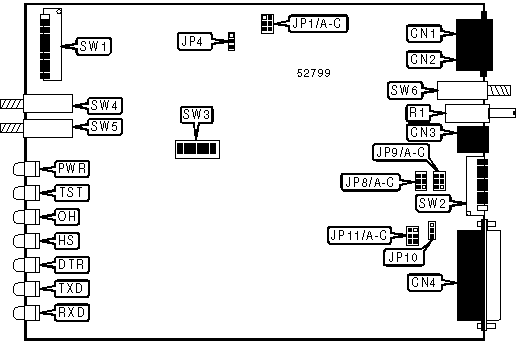
CONNECTIONS | |||
|
Function |
Label |
Function |
Label |
|
Line out |
CN1 |
Volume control |
R1 |
|
Line in |
CN2 |
Talk/Data switch |
SW4 |
|
AC power in |
CN3 |
Originate/Answer switch |
SW5 |
|
RS232/422 port |
CN4 |
Reset switch |
SW6 |
|
USER CONFIGURABLE SETTINGS | ||
|
Setting |
Label |
Position |
|
Minimum receive signal level set to -43 dBm |
JP4 |
Pins 1 & 2 closed |
|
Minimum receive signal level set to -33 dBm |
JP4 |
Pins 2 & 3 closed |
|
í Factory configured - do not alter |
JP8/A |
Closed |
|
í Factory configured - do not alter |
JP8/B |
Open |
|
í Factory configured - do not alter |
JP8/C |
Open |
|
í Factory configured - do not alter |
JP9/A |
Closed |
|
í Factory configured - do not alter |
JP9/B |
Open |
|
í Factory configured - do not alter |
JP9/C |
Open |
|
USER CONFIGURABLE SETTINGS (CON’T) | ||
|
Setting |
Label |
Position |
|
Pin 1 of serial port connected to signal ground |
JP10 |
Pins 2 & 3 closed |
|
Pin 1 of serial port connected to chassis ground |
JP10 |
Pins 1 & 2 closed |
|
Pin 18 has no function |
JP11/A |
Open |
|
Modem performs local analog loopback test when pin 18 goes high |
JP11/A |
Closed |
|
í Factory configured - do not alter (for North America) |
SW3/7 |
On |
|
í Factory configured - do not alter (for North America) |
SW3/8 |
On |
Note: If pin 18 is enabled, busy out must be disabled. | ||
|
LINE TYPE SELECTION | |||
|
Setting |
JP1/A |
JP1/B |
JP1/C |
|
Leased line (0 dBm) |
Open |
Open |
Closed |
|
Permissive (-10 dBm) |
Closed |
Open |
Open |
|
Programmable (-12 dBm) |
Open |
Closed |
Open |
|
BUSY OUT SELECTION | ||
|
Setting |
JP11/B |
JP11/C |
|
Busy out enabled |
Closed |
Open |
|
Busy out disabled |
Open |
Closed |
Note: If busy out is enabled, pin 18 must be disabled. | ||
|
LEASED LINE TRANSMISSION LEVEL SELECTION | |||
|
Setting |
SW3/1 |
SW3/2 |
SW3/3 |
|
-2 dBm |
On |
On |
On |
|
-4 dBm |
Off |
On |
On |
|
-6 dBm |
On |
Off |
On |
|
-8 dBm |
Off |
Off |
On |
|
-10 dBm |
On |
On |
Off |
|
-12 dBm |
Off |
On |
Off |
|
-14 dBm |
On |
Off |
Off |
|
-16 dBm |
Off |
Off |
Off |
|
SWITCHED LINE TRANSMISSION LEVEL SELECTION | |||
|
Setting |
SW3/4 |
SW3/5 |
SW3/6 |
|
-2 dBm |
On |
On |
On |
|
-4 dBm |
Off |
On |
On |
|
-6 dBm |
On |
Off |
On |
|
-8 dBm |
Off |
Off |
On |
|
-10 dBm |
On |
On |
Off |
|
-12 dBm |
Off |
On |
Off |
|
-14 dBm |
On |
Off |
Off |
|
-16 dBm |
Off |
Off |
Off |
|
CONFIGURATION MODE FUNCTION | |
|
Mode |
Function |
|
0 |
Normal operation of modem - sets power-up defaults for various commands |
|
1 |
Sets user profile that will be loaded at power-up |
|
2 |
Performs diagnostic tests |
|
3 |
Modifies factory default settings loaded by &F command |
|
4 |
Sets power-up defaults for V.25bis synchronous and dumb synchronous modes |
Note: The QX/4232bis+ modem can be configured by switches in five modes, although command configuration is preferable when possible. Configuration modes 1, 3, and 4 can be stored in NVRAM by pressing the reset switch. Mode 0 is read on reset or power-up. Before operating, the modem’s switches should be returned to mode 0 and the appropriate settings made. | |
|
CONFIGURATION MODE SELECTION | ||||||
|
Mode |
Command Set |
Async/Sync |
SW1/1 |
SW1/2 |
SW1/3 |
SW1/9 |
|
0 |
AT |
Async |
See mode 0 |
Off |
On |
On |
|
0 |
V.25bis |
Async |
See mode 0 |
On |
On |
On |
|
1 |
N/A |
N/A |
Off |
Off |
Off |
On |
|
2 |
N/A |
Async |
See mode 2 |
On |
Off |
On |
|
2 |
N/A |
Sync |
See mode 2 |
On |
Off |
Off |
|
3 |
N/A |
N/A |
On |
Off |
Off |
On |
|
4 |
V.25bis |
Sync |
See mode 4 |
On |
On |
Off |
|
4 |
None |
Sync |
See mode 4 |
Off |
On |
Off |
Configuration Mode 0 - Normal Operation
|
USER CONFIGURABLE SETTINGS | ||
|
Setting |
Label |
Position |
|
í Modem goes to command mode and disconnects on low DTR |
SW1/1 |
On |
|
Modem ignores DTR |
SW1/1 |
Off |
|
í Command echo enabled |
SW1/4 |
On |
|
Command echo disabled |
SW1/4 |
Off |
|
í Auto-answer on one ring |
SW1/5 |
On |
|
Auto-answer disabled |
SW1/5 |
Off |
|
í Command sets enabled |
SW1/8 |
Off |
|
Command sets disabled |
SW1/8 |
On |
|
í Originate/Answer button determines mode |
SW1/10 |
On |
|
Force answer mode |
SW1/10 |
Off |
|
í Error correction result codes enabled |
SW2/5 |
Off |
|
Extended result codes disabled |
SW2/5 |
On |
|
í User profile loaded on reset and power up |
SW2/6 |
On |
|
Factory profile loaded on reset and power up |
SW2/6 |
Off |
|
í Switch configuration enabled |
SW2/7 |
Off |
|
Switch configuration disabled |
SW2/7 |
On |
|
í Serial port speed locked |
SW2/8 |
Off |
|
Serial port speed follows connect speed |
SW2/8 |
On |
Note: SW2/8 has no function in V.25bis mode. | ||
|
CD, CTS, AND DSR SIGNAL CONFIGURATION | ||
|
Setting |
SW1/6 |
SW1/7 |
|
CD, CTS, and DSR forced high |
On |
On |
|
CD normal, CTS follows CD, DSR follows OH |
On |
Off |
|
CD, CTS, and DSR forced high except at disconnect |
Off |
On |
|
í CD normal, CTS and DSR forced high |
Off |
Off |
|
FLOW CONTROL SELECTION | ||
|
Setting |
SW2/1 |
SW2/2 |
|
Flow control disabled |
On |
On |
|
Bidirectional XON/XOFF flow control enabled |
On |
Off |
|
í Bidirectional RTS/CTS flow control enabled |
Off |
On |
|
CTS flow control by DCE enabled |
Off |
Off |
|
CONNECT MODE SELECTION | ||
|
Setting |
SW2/3 |
SW2/4 |
|
Normal mode enabled |
On |
On |
|
MNP reliable mode enabled |
On |
Off |
|
í Auto-reliable mode enabled |
Off |
On |
|
LAPM or MNP reliable mode |
Off |
Off |
Configuration Mode 1 - User Profile
|
USER CONFIGURABLE SETTINGS | ||
|
Setting |
Label |
Position |
|
í Factory configured - do not alter |
SW1/6 |
N/A |
|
í Factory configured - do not alter |
SW1/7 |
N/A |
|
í Factory configured - do not alter |
SW1/8 |
N/A |
|
í Originate/Answer button determines mode |
SW1/10 |
On |
|
Force answer mode |
SW1/10 |
Off |
|
í Factory configured - do not alter |
SW2/1 |
N/A |
|
í Factory configured - do not alter |
SW2/2 |
N/A |
|
í Factory configured - do not alter |
SW2/3 |
N/A |
|
í Factory configured - do not alter |
SW2/4 |
N/A |
|
í Factory configured - do not alter |
SW2/5 |
N/A |
|
í Factory configured - do not alter |
SW2/6 |
N/A |
|
í Factory configured - do not alter |
SW2/7 |
N/A |
|
í Factory configured - do not alter |
SW2/8 |
N/A |
|
USER PROFILE SELECTION | ||
|
Setting |
SW1/4 |
SW1/5 |
|
User profile 0 |
On |
On |
|
User profile 1 |
On |
Off |
|
User profile 2 |
Off |
On |
|
User profile 3 |
Off |
Off |
Configuration Mode 2 - Diagnostic Testing
|
TOGGLE SWITCHES | ||||||
|
Function |
Label |
Function |
Label | |||
|
Start or stop test in progress |
SW1/1 |
Start or stop test in progress |
SW4 | |||
|
USER CONFIGURABLE SETTINGS | ||
|
Setting |
Label |
Position |
|
Modem will perform local digital loopback test |
SW1/4 |
Off |
|
Modem will not perform local digital loopback test |
SW1/4 |
On |
|
Modem will perform local analog loopback test |
SW1/5 |
Off |
|
Modem will not perform local analog loopback test |
SW1/5 |
On |
|
SW1/5 performs local analog loopback with self-test |
SW1/6 |
Off |
|
SW1/5 performs local analog loopback test |
SW1/6 |
On |
|
í Factory configured - do not alter |
SW1/7 |
N/A |
|
í Factory configured - do not alter |
SW1/8 |
N/A |
|
í Factory configured - do not alter |
SW1/10 |
N/A |
|
í Factory configured - do not alter |
SW2/1 |
N/A |
|
í Factory configured - do not alter |
SW2/2 |
N/A |
|
í Factory configured - do not alter |
SW2/3 |
N/A |
|
í Factory configured - do not alter |
SW2/4 |
N/A |
|
í Factory configured - do not alter |
SW2/5 |
N/A |
|
í Factory configured - do not alter |
SW2/6 |
N/A |
|
í Factory configured - do not alter |
SW2/7 |
N/A |
|
í Factory configured - do not alter |
SW2/8 |
N/A |
Note: The modem will conduct tests in synchronous or asynchronous mode according to where SW1/9 was set the last time it was reset. | ||
Configuration Mode 3 - Factory Default Modification
|
USER CONFIGURABLE SETTINGS | ||
|
Setting |
Label |
Position |
|
Verbose result codes enabled |
SW1/6 |
On |
|
Numeric result codes enabled |
SW1/6 |
Off |
|
Pins 18 and 21 have no function |
SW1/7 |
On |
|
Perform local analog loopback test when pin 18 is high, remote digital loopback test when pin 21 is high |
SW1/7 |
Off |
|
\K set to 0 |
SW1/8 |
Off |
|
\K set to 5 |
SW1/8 |
On |
|
Originate/Answer button determines mode |
SW1/10 |
On |
|
Force answer mode |
SW1/10 |
Off |
|
Inactivity timer disabled |
SW2/1 |
On |
|
Inactivity timer set to 15 minutes |
SW2/1 |
Off |
|
Modem-to-modem flow control disabled |
SW2/2 |
On |
|
Modem-to-modem flow control enabled |
SW2/2 |
Off |
|
Parity checking of flow control and escape characters disabled |
SW2/3 |
On |
|
Flow control and escape characters will be processed only if their parity matches serial port |
SW2/3 |
Off |
|
RESULT CODE CONFIGURATION | ||
|
Setting |
SW1/4 |
SW1/5 |
|
Result codes enabled |
On |
On |
|
Result codes disabled |
On |
Off |
|
Result codes enabled on originate only |
Off |
N/A |
|
PARITY SELECTION | |||
|
Setting |
SW2/4 |
SW2/5 |
SW2/6 |
|
Modem will use eight data bits, no parity |
On |
On |
On |
|
Modem will use seven data bits, odd parity |
On |
On |
Off |
|
Modem will use seven data bits, even parity |
On |
Off |
On |
|
Modem will use seven data bits, MARK parity |
On |
Off |
Off |
|
Modem will use seven data bits, SPACE parity |
Off |
On |
On |
|
Modem will use eight data bits, odd parity |
Off |
On |
Off |
|
Modem will use eight data bits, even parity |
Off |
Off |
On |
|
Modem will use eight data bits, MARK parity |
Off |
Off |
Off |
|
SPEED SELECTION | ||
|
Setting |
SW2/7 |
SW2/8 |
|
Serial port speed set to 38.4Kbps; line speed set to 14.4Kbps |
On |
On |
|
Serial port speed set to 19.2Kbps; line speed set to 14.4Kbps |
On |
Off |
|
Serial port and line speeds set to 9600bps |
Off |
On |
|
Serial port speed set to 57.6Kbps; line speed set to 14.4Kbps |
Off |
Off |
Configuration Mode 4 - Synchronous Mode
|
USER CONFIGURABLE SETTINGS | ||
|
Setting |
Label |
Position |
Modem goes to command mode and disconnects on low-to-high DTR transition |
SW1/1 |
On |
|
Modem ignores DTR |
SW1/1 |
Off |
|
Originate/Answer button determines mode |
SW1/10 |
On |
|
Force answer mode |
SW1/10 |
Off |
|
Pins 18 and 21 have no function |
SW2/3 |
On |
Perform local analog loopback test when pin 18 is high, remote digital loopback test when pin 21 is high |
SW2/3 |
Off |
|
Auto-answer on one ring |
SW2/7 |
Off |
|
Auto-answer disabled |
SW2/7 |
On |
|
Modem will match connect speeds. |
SW2/8 |
On |
|
Modem will connect only at current speed. |
SW2/8 |
Off |
|
STORED NUMBER SELECTION | ||
|
Setting |
SW1/4 |
SW1/5 |
|
Manual dial only |
On |
On |
|
Dial first stored number when Talk/Data switch is pressed |
On |
Off |
|
Dial second stored number when Talk/Data switch is pressed |
Off |
On |
|
Dial third stored number when Talk/Data switch is pressed |
Off |
Off |
|
LINE TYPE SELECTION | |||
|
Setting |
SW1/6 |
SW1/7 |
SW1/8 |
|
Modem is connected to switched line |
On |
On |
On |
|
Modem is connected to 2-wire leased line |
Off |
On |
On |
|
Modem is connected to 4-wire leased line |
Off |
Off |
On |
|
Modem is connected to 2-wire leased line. After 6 seconds of receiving no input, the modem goes off-hook and attempts to connect. |
On |
Off |
On |
|
Modem is connected to 4-wire leased line. After 6 seconds of receiving no input, the modem goes off-hook and attempts to connect. |
On |
On |
Off |
|
CONNECT SPEED SELECTION | ||
|
Setting |
SW2/1 |
SW2/2 |
|
Modem will connect at 14.4Kbps |
On |
On |
|
Modem will connect at 9600bps |
On |
Off |
|
Modem will connect at 4800bps |
Off |
On |
|
Modem will connect at 2400bps |
Off |
Off |
|
CD, CTS, DSR, AND RTS SIGNAL CONFIGURATION | |||
|
Setting |
SW2/4 |
SW2/5 |
SW2/6 |
|
CD, CTS, and DSR forced high |
On |
On |
On |
|
CD, CTS, and DSR normal |
On |
On |
Off |
|
CD, CTS, and DSR forced high except at disconnect |
On |
Off |
On |
|
CD normal, CTS and DSR forced high |
On |
Off |
Off |
|
CD, CTS, and DSR normal |
Off |
On |
On |
|
CD normal, CTS follows RTS, DSR forced high |
Off |
On |
Off |
|
CD and CTS use ITU-T V.13 to simulate half-duplex modes, DSR normal |
Off |
Off |
On |
|
CD and CTS use ITU-T V.13 to simulate half-duplex modes, DSR forced high |
Off |
Off |
Off |
|
DIAGNOSTIC LED(S) (POWER-UP) | |||
|
TST |
OH |
HS |
Condition |
|
On |
Off |
Off |
Firmware checksum incorrect |
|
On |
Off |
Red |
RAM test failed |
|
On |
Off |
Green |
Modem failed |
|
On |
On |
N/A |
Modem failed |
|
Off |
Off |
Off |
All tests passed |
|
DIAGNOSTIC LED(S) (NORMAL OPERATION) | |||
|
LED |
Color |
Status |
Condition |
|
PWR |
Unidentified |
On |
Power is on |
|
PWR |
Unidentified |
Off |
Power is off |
|
TST |
Unidentified |
On |
System error has occurred or modem is retraining |
|
TST |
Unidentified |
Blinking |
Serial port is waiting to be configured |
|
TST |
Unidentified |
One blink |
Data error has occurred |
|
TST |
Unidentified |
Off |
Normal operation |
|
OH |
Unidentified |
On |
Modem is off-hook |
|
OH |
Unidentified |
Off |
Modem is on-hook |
|
HS |
Red |
On |
Modem is connected at, or serial port speed is set to, 300bps |
|
HS |
Red |
1 blink |
Modem is connected at, or serial port speed is set to, 600bps |
|
HS |
Red |
2 blinks |
Modem is connected at, or serial port speed is set to, 1200bps |
|
HS |
Red |
3 blinks |
Modem is connected at, or serial port speed is set to, 2400bps |
|
HS |
Green |
On |
Modem is connected at, or serial port speed is set to, 4800bps |
|
HS |
Green |
1 blink |
Modem is connected at, or serial port speed is set to, 7200bps |
|
HS |
Green |
2 blinks |
Modem is connected at, or serial port speed is set to, 9600bps |
|
HS |
Green |
3 blinks |
Modem is connected at, or serial port speed is set to, 12Kbps |
|
HS |
Green |
4 blinks |
Modem is connected at, or serial port speed is set to, 14.4Kbps |
|
HS |
N/A |
Off |
Modem is connected at, or serial port speed is set to, 75bps |
|
DTR |
Unidentified |
On |
DTR signal is high |
|
DTR |
Unidentified |
Off |
DTR signal is low |
|
TXD |
Unidentified |
Blinking |
Modem is transmitting data |
|
TXD |
Unidentified |
Off |
Modem is not transmitting data |
|
RXD |
Unidentified |
Blinking |
Modem is receiving data |
|
RXD |
Unidentified |
Off |
Modem is not receiving data |
|
SUPPORTED STANDARD COMMANDS |
|
Basic AT Commands |
|
+++, ‘comma’, A/ |
|
A, B, E, H, I, L, M, O, P, Q, T, V, W, X, Y, Z |
|
&D, &F, &G, &M, &P, &T, &W, &X, &Y, &Z |
|
Extended AT Commands |
|
\A, \B, \C, \E, \J, \N, \Q, \T |
|
%A, %C, %E, %F, %G |
|
Special AT Commands |
|
-J, *H, )M, @M, :E |
|
S-Registers |
|
S0, S1, S2, S3, S4, S5, S6, S7, S8, S9, S10, S12, S14, S16, S18, S22, S23, S25, S26, S27 |
Note: See MHI documentation for complete information. |
Proprietary AT Command Set
|
COMMAND SET - V.25bis | |
|
Type: |
Immediate |
|
Format: |
[cmds] \M |
|
Description: |
Enables the V.25bis command set. |
|
DISPLAY SWITCH SETTINGS | ||
|
Type: |
Immediate | |
|
Format: |
AT [cmds] %Sn [cmds] | |
|
Description: |
Displays the modem’s switch settings. | |
|
Command |
Function | |
|
%S0 |
Display settings of SW1/1-SW1/10. | |
|
%S1 |
Display settings of SW2/1-SW2/8. | |
|
%S2 |
Display settings of SW3/1-SW3/8. | |
|
LEASED LINE CALL RESTORAL | ||
|
Type: |
Configuration | |
|
Format: |
AT [cmds] )Pn [cmds] | |
|
Description: |
Selects whether the modem will attempt to reconnect with a dial backup call to a leased line MNP reliable mode connection that has terminated abnormally. If the dial backup reconnects successfully, the call will proceed as if it had not disconnected. | |
|
Command |
Function | |
|
)P0 |
Leased line call restoral disabled. | |
|
í )P1 |
Leased line call restoral enabled. | |
|
LEASED LINE COMPROMISE EQUALIZER | ||
|
Type: |
Configuration | |
|
Format: |
AT [cmds] )En [cmds] | |
|
Description: |
Selects whether the compromise equalizer will be used for leased line V.32 and V.32bis connections. | |
|
Command |
Function | |
|
í )E0 |
Compromise equalizer disabled. | |
|
)E1 |
Compromise equalizer enabled. | |
|
LEASED LINE DIAL BACKUP | ||
|
Type: |
Configuration | |
|
Format: |
AT [cmds] :Nn [cmds] | |
|
Description: |
Selects whether the modem will attempt to connect to the first stored number with a switched line connection if the leased line connection fails. | |
|
Command |
Function | |
|
:N0 |
Dial backup disabled. | |
|
í :N1 |
Dial backup enabled. | |
|
LEASED LINE DIAL BACKUP IN ANSWER MODE | ||
|
Type: |
Configuration | |
|
Format: |
AT [cmds] )Cn [cmds] | |
|
Description: |
Selects whether the modem is allowed to execute a dial backup if it is in answer mode. | |
|
Command |
Function | |
|
)C0 |
Dial backup disabled in answer mode. | |
|
í )C1 |
Dial backup enabled in answer mode. | |
|
LEASED LINE MAXIMUM RETRAIN COUNTER | |
|
Type: |
Configuration |
|
Format: |
AT [cmds] :Gn [cmds] |
|
Description: |
Sets the number of times the modem is allowed to retrain in the time specified by the :H command before it attempts a dial backup connection. |
|
LEASED LINE MAXIMUM RETRAIN TIME | |
|
Type: |
Configuration |
|
Format: |
AT [cmds] :Hn [cmds] |
|
Default: |
0 |
|
Range: |
0 - 255 |
|
Unit: |
1 minute |
|
Description: |
Sets the amount of time in which the modem is allowed to retrain the number of times specified by the :G command before it attempts a dial backup connection. |
|
LEASED LINE ORIGINATE MODE TIMER | |
|
Type: |
Configuration |
|
Format: |
AT [cmds] &Vn [cmds] |
|
Default: |
5 |
|
Range: |
0 - 90 |
|
Unit: |
1 minute |
|
Description: |
Sets the amount of time that the originating modem waits for an answer before attempting a dial backup. |
|
LEASED LINE QUALITY | |
|
Type: |
Immediate |
|
Format: |
AT [cmds] )F [cmds] |
|
Default: |
N/A |
|
Range: |
0 - 65535 |
|
Unit: |
N/A |
|
Description: |
Displays the poorest quality of the phone line this connection. Higher numbers indicate a poorer connection. |
|
LEASED LINE QUALITY CLEAR | |
|
Type: |
Configuration |
|
Format: |
AT [cmds] :Y [cmds] |
|
Description: |
Clears the line quality value reported by )F so that the current line quality may be monitored. |
|
LEASED LINE RESTORAL | ||
|
Type: |
Configuration | |
|
Format: |
AT [cmds] )Ln [cmds] | |
|
Description: |
Selects whether the modem will attempt to restore a leased line connection while connected with a dial backup connection. | |
|
Command |
Function | |
|
)L0 |
Modem will not attempt to restore leased line connection. | |
|
í )L1 |
Modem will attempt to restore leased line connection. | |
|
LEASED LINE RESTORAL CARRIER TIMER | |
|
Type: |
Configuration |
|
Format: |
AT [cmds] )Wn [cmds] |
|
Default: |
20 |
|
Range: |
0 - 255 |
|
Unit: |
1 second |
|
Description: |
Sets the amount of time that the modem waits for a carrier after attempting to restore a leased line connection. If this time expires the modem will begin a dial backup again. |
|
LEASED LINE RESTORAL DELAY | |
|
Type: |
Configuration |
|
Format: |
AT [cmds] )Xn [cmds] |
|
Default: |
60 |
|
Range: |
0 - 60 |
|
Unit: |
1 minute |
|
Description: |
Sets the amount of time that the modem waits after a successful dial backup to check the leased line to see if service has been re-established. |
|
LEASED LINE RESTORAL RETRY DELAY | |
|
Type: |
Configuration |
|
Format: |
AT [cmds] )Yn [cmds] |
|
Default: |
40 |
|
Range: |
0 - 255 |
|
Unit: |
1 second |
|
Description: |
Sets the amount of time after a failed attempt to re-connect to the leased line, and while it is performing a dial backup, that the modem watches for a carrier on the leased line. If no carrier is detected within this time the modem proceeds with the dial backup. |
|
LEASED LINE RESTORE | |
|
Type: |
Immediate |
|
Format: |
AT [cmds] )B [cmds] |
|
Description: |
Initiates a leased line restoral. |
|
LINE TYPE | ||
|
Type: |
Configuration | |
|
Format: |
AT [cmds] &Ln [cmds] | |
|
Description: |
Selects what type of line the modem is connected to and whether it will attempt to automatically re-connect. | |
|
Command |
Function | |
|
í &L0 |
Modem is connected to switched line. | |
|
&L1 |
Modem is connected to 2-wire leased line. | |
|
&L2 |
Modem is connected to 4-wire leased line. | |
|
&L3 |
Modem is connected to 2-wire leased line. After 6 seconds of receiving no input, the modem goes off-hook and attempts to connect. | |
|
&L4 |
Modem is connected to 4-wire leased line. After 6 seconds of receiving no input, the modem goes off-hook and attempts to connect. | |
|
OPERATING MODE | ||
|
Type: |
Configuration | |
|
Format: |
AT [cmds] $Sn [cmds] | |
|
Description: |
Selects whether the modem will operate in asynchronous or synchronous mode. | |
|
Command |
Function | |
|
í $S0 |
Determined by SW1/9. | |
|
$S1 |
Force asynchronous mode. | |
|
$S2 |
Force synchronous mode. | |
Proprietary V.25bis Command Set
|
COMMAND SET - AT | |
|
Type: |
Immediate |
|
Format: |
ATZ |
|
Description: |
Enables the AT command set. |
|
CONNECTION SECURITY - PASSWORD SELECTION (ASYNCHRONOUS MODE) | |
|
Type: |
Configuration |
|
Format: |
PSW |
|
Description: |
Changes the connection password. The user will be prompted to enter the old and new passwords. Passwords must be exactly five characters, case insensitive. |
|
CONNECTION SECURITY - PASSWORD SELECTION (SYNCHRONOUS MODE) | |
|
Type: |
Configuration |
|
Format: |
PSWxxxxx;yyyyy |
|
Description: |
Changes the connection password. The xxxxx represents old connection password, and the yyyyy is the new connection password. Passwords must be exactly five characters, case insensitive. |
See MICROCOM, INC. DESKPORTE FAST for a full command summary.