HAYES MICROCOMPUTER PRODUCTS, INC.
ULTRA SMARTMODEM 14400
|
Modem Type |
Data (synchronous/asynchronous) |
|
Maximum Data Rate |
14.4Kbps |
|
Data Bus |
External |
|
Data Modulation Protocol |
Bell 103A/212A ITU-T V.21, V.22, V.22bis, V.23, V.32, V.32bis |
|
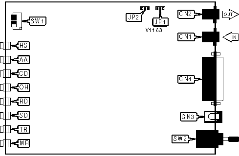
CONNECTIONS | |||
|
Purpose |
Location |
Purpose |
Location |
|
Line in |
CN1 |
RS-232 |
CN4 |
|
Line out |
CN2 |
Power switch |
SW2 |
|
DC power |
CN3 | ||
|
COMMAND SETS | |
| Mode |
SW1/1 |
| » Enabled |
On |
| Disabled |
Off |
|
LEASED LINE CARRIER TRANSMIT LEVEL ADJUSTMENT | |
| Mode |
SW1/2 |
| » Disabled |
On |
| Enabled |
Off |
|
COMMAND MODE | ||
| Mode |
SW1/3 |
SW1/4 |
|
AT command set |
Off |
Off |
|
Asynchronous V.25 command set |
Off |
On |
|
Synchronous V.25 command set w/HDLC framing |
On |
Off |
|
Synchronous V.25 command set w/character framing |
On |
On |
|
MI/MIC | ||
| Mode |
JP1 |
JP2 |
| » Disabled |
Pins 1 & 2 closed |
Pins 1 & 2 closed |
| Enabled |
Pins 2 & 3 closed |
Pins 2 & 3 closed |
|
DIAGNOSTIC LED(S) | |||
|
LED |
Color |
Status |
Condition |
|
HS |
Red |
On |
Modem is operating at 4800bps or faster |
|
HS |
Red |
Off |
Modem is operating at slower than 4800bps |
|
AA |
Red |
On |
Auto-answer enabled |
|
AA |
Red |
Off |
Auto-answer disabled |
|
AA |
Red |
Blinking |
Line is ringing |
|
CD |
Red |
On |
CD signal is high |
|
CD |
Red |
Off |
CD signal is low |
|
OH |
Red |
On |
Modem is off-hook |
|
OH |
Red |
Off |
Modem is on-hook |
|
RD |
Red |
On |
Modem is receiving data |
|
RD |
Red |
Off |
Modem is not receiving data |
|
SD |
Red |
On |
Modem is transmitting data |
|
SD |
Red |
Off |
Modem is not transmitting data |
|
TR |
Red |
On |
DTR signal is high |
|
TR |
Red |
Off |
DTR signal is low |
|
MR |
Red |
On |
Power is on |
|
MR |
Red |
Off |
Power is off |
Proprietary AT Command Set
|
COMMAND MODE OPTIONS | |||
|
Format |
AT [cmds] S94=n [cmds] | ||
|
Example: |
ATS94=40 <CR> | ||
|
Default: |
0 | ||
|
Range: |
0 - 15 | ||
|
Unit: |
Bit-mapped | ||
|
Description: |
Sets various options for command set modes. | ||
|
Bit | Value |
Function | |
|
1, 0 | » 00 01 10 11 |
Use AT command set. Use asynchronous V.25 command set. Use synchronous V.25 command set with HDLC framing. Use synchronous V.25 command set with character framing. | |
|
2 | » 0 1 |
Addressed calling. Direct access calling. | |
|
3 | » 0 1 |
Use ASCII character set. Use EBCDIC character set. | |
|
RESTART REQUEST ACKNOWLEDGEMENT TIME | |
|
Type: |
Register |
|
Format: |
AT [cmds] S81=n [cmds] |
|
Example: |
ATS81=15 <CR> |
|
Default: |
18 |
|
Range: |
0-255 |
|
Unit: |
10 seconds |
|
Description: |
Sets the time the transmitting modem will wait for acknowledgement of its restart request before it initiates a recovery. |
|
RESTART REQUEST MAXIMUM | |
|
Type: |
Register |
|
Format: |
AT [cmds] S80=n [cmds] |
|
Example: |
ATS80=8 <CR> |
|
Default: |
1 |
|
Range: |
0-255 |
|
Unit: |
N/A |
|
Description: |
Sets the number of times a restart request can be retransmitted. |
|
V.22 PROBE REJECT TIME | |
|
Type: |
Register |
|
Format: |
AT [cmds] S97=n [cmds] |
|
Example: |
ATS97=15 <CR> |
|
Default: |
30 |
|
Range: |
15-70 |
|
Unit: |
.1 second |
|
Description: |
Sets the time for which the modem will reject the V.22/V.22bis probe signal when in V.32 mode. |
|
V.25 OPTIONS | |||
|
Format |
AT [cmds] S115=n [cmds] | ||
|
Example: |
ATS115=40 <CR> | ||
|
Default: |
0 | ||
|
Range: |
0 - 3 | ||
|
Unit: |
Bit-mapped | ||
|
Description: |
Sets V.25 data mode and V.25 auto-answer mode. | ||
|
Bit | Value |
Function | |
|
0 | » 0 1 |
Answer after two rings Answer after number of rings set in S0. | |
|
1 | » 0 1 |
Select 7 data bits, even parity, and one stop bit. Select 8 data bits, no parity, and one stop bit. | |
Proprietary V.25bis Command Set
|
RESET TO AT COMMAND SET | |
|
Type: |
Immediate |
|
Format: |
RST |
|
Example: |
RST <CR> |
|
Description: |
Executes a cold reset and returns to AT command set. |