ACEEX CORPORATION
ISDN-TA/MLP
|
Card Type |
ISDN TA |
|
Chip Set |
Unidentified |
|
I/O Options |
AC power, power switch, 26-pin serial port, ISDN S/T interface (RJ-45) analog telephone port (RJ-11), |
|
ISDN Data Rate |
128Kbps |
|
ISDN Modulation Protocol |
V.110, V.120, X.75, HDLC, PPP, MLPPP |
|
Error Correction/Compression |
MNP5, V.42bis |
|
Data Bus |
External |
|
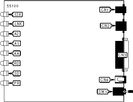
CONNECTIONS | |||
|
Function |
Label |
Function |
Label |
|
Analog telephone interface (RJ-11 connector) |
CN1 |
AC power |
CN4 |
|
ISDN S/T interface (RJ-45 connector) |
CN2 |
Power switch |
SW1 |
|
25-pin serial port |
CN3 | ||
|
Note: RJ-11 modular cable splits the analog telephone interface (CN1) into two ports. | |||
|
DIAGNOSTIC LED(S) | |||
|
LED |
Color |
Status |
Condition |
|
PR |
Unidentified |
On |
Power is on |
|
PR |
Unidentified |
Off |
Power is off |
|
SD |
Unidentified |
On |
TA is transmitting data to a remote computer |
|
SD |
Unidentified |
Off |
TA is not transmitting data to a remote computer |
|
RD |
Unidentified |
On |
TA is receiving data from remote computer |
|
RD |
Unidentified |
Off |
TA is not receiving data from a remote computer |
|
AA |
Unidentified |
On |
Auto answer enabled |
|
AA |
Unidentified |
Blinking |
Phone is ringing |
|
AA |
Unidentified |
Off |
Auto answer disabled |
|
A1 |
Unidentified |
On |
Telephone port 1 is active |
|
A1 |
Unidentified |
Blinking |
Call is in progress on telephone port 1 |
|
A1 |
Unidentified |
Off |
Telephone port 1 is idle |
|
A2 |
Unidentified |
On |
Telephone port 2 is active |
|
A2 |
Unidentified |
Blinking |
Call is in progress on telephone port 2 |
|
A2 |
Unidentified |
Off |
Telephone port 2 is idle |
|
LNK |
Unidentified |
On |
ISDN S/T interface is active |
|
LNK |
Unidentified |
Off |
ISDN S/T interface is idle |
|
128 |
Unidentified |
On |
MLPPP enabled |
|
128 |
Unidentified |
Off |
MLPPP disabled |
|
SUPPORTED COMMAND SET |
|
Basic AT Commands |
|
AT, A/ |
|
A, E, Q, V |
|
&C, &F, &R, &V, &Z |
|
S Registers |
|
S0, S2, S3, S4, S5, S12, S25, S26, S32, S33 |
|
Note: See MHI Help File for full command documentation. |
Proprietary AT Command Set
|
CHAP NEGOTIATION | |
|
Type: |
Configuration |
|
Format: |
AT [cmds] &Pn [cmds] |
|
Description: |
Enables/disables CHAP negotiation |
|
Command |
Function |
|
&P0 |
CHAP negotiation enabled |
|
&P1 |
CHAP negotiation disabled |
|
COMMUNICATIONS MODE | |
|
Type: |
Configuration |
|
Format: |
AT [cmds] &Mn [cmds] |
|
Description: |
Selects communications mode |
|
Command |
Mode |
|
í &M0 |
Asynchronous mode |
|
&M1 |
Synchronous connect mode and asynchronous off-line command mode. |
|
&M2 |
Synchronous connect mode |
|
DATA SET READY (DSR) | |
|
Type: |
Configuration |
|
Format: |
AT [cmds] &Sn [cmds] |
|
Description: |
Selects DSR options |
|
Command |
Function |
|
&S0 |
DSR forced high |
|
&S1 |
DSR high only while modem is connected |
|
DATA TERMINAL READY (DTR) | ||
|
Type: |
Configuration | |
|
Format: |
AT [cmds] &Dn [cmds] | |
|
Description: |
Selects modem response to DTR | |
|
Command |
Mode | |
|
í &D2 |
Abort connection on low DTR after time specified by register S25 | |
|
DIAL | ||
|
Type: |
Immediate | |
|
Format: |
AT [cmds] D<#> [cmds] | |
|
Description: |
Dials telephone number according to any modifiers included in the string | |
|
Command |
Function | |
|
DT |
Dials telephone number (same as ATD) | |
|
DP |
Dials telephone number (same as ATD) | |
|
DS |
Dial stored telephone number | |
|
FLOW CONTROL | |
|
Type: |
Configuration |
|
Format: |
AT [cmds] &Kn [cmds] |
|
Description: |
Enables flow control options |
|
Command |
Function |
|
&K0 |
Flow control disabled |
|
í &K3 |
RTS/CTS flow control enabled |
|
&K4 |
XON/XOFF flow control enabled |
|
&K5 |
Transparent XON/XOFF flow control enabled |
|
&K6 |
RTS/CTS & XON/XOFF flow control enabled |
|
HOOK CONTROL | |
|
Type: |
Immediate |
|
Format: |
AT [cmds] Hn [cmds] |
|
Description: |
Selects whether the modem is on-hook or off-hook |
|
Command |
Function |
|
H0 |
Modem commanded to go on-hook (hang-up) |
|
ON-LINE | |
|
Type: |
Immediate |
|
Format: |
AT [cmds] On [cmds] |
|
Description: |
Controls on-line command (data transmission) state options. |
Note: The O command must be placed at the end of the command string. | |
|
Command |
Function |
|
O0 |
On-line command mode with no retraining enabled |
|
REPORT INFORMATION | |
|
Type: |
Immediate |
|
Format: |
AT [cmds] In [cmds] |
|
Description: |
Displays information requested |
|
Command |
Function |
|
I0 |
Reports product identification |
|
I1 |
Reports ROM checksum |
|
I3 |
Reports model function |
|
I6 |
Reports product name |
|
SELECT CALL PROGRESS RESULT CODES | |
|
Type: |
Configuration |
|
Format: |
AT [cmds] Xn [cmds] |
|
Description: |
Enables selection of tone detection and associated result code format options |
|
Command |
Function |
|
X0 |
Base result codes only |
|
X1 |
Extended result codes enabled |
|
X2 |
Extended ISDN result codes enabled |
|
SOFT RESET | |
|
Type: |
Immediate |
|
Format: |
AT [cmds] Zn [cmds] |
|
Description: |
Resets the active configuration to the stored configuration |
|
STORE ACTIVE PROFILE | |
|
Type: |
Configuration |
|
Format: |
AT [cmds] &Wn [cmds] |
|
Description: |
Writes the values for the active profile into the non-volatile RAM |
|
V.110 LINE SPEED | |
|
Type: |
Configuration |
|
Format: |
AT [cmds] Fn [cmds] |
|
Description: |
Sets the maximum allowable data exchange rate for V.110 modulation |
|
Command |
Function |
|
F0 |
V.110 network baud rate follows DCE to a maximum of 38.4bps |
|
F1 |
300bps |
|
F2 |
1200bps |
|
F3 |
2400bps |
|
F4 |
4800bps |
|
F5 |
9600bps |
|
F6 |
19.2Kbps |
|
F7 |
38.4Kpbs |
Special Commands
|
ISDN PROTOCOL SELECTION | ||
|
Type: |
Configuration | |
|
Format: |
AT [cmds] !Z=n [cmds] | |
|
Description: |
Sets the B-channel protocol | |
|
Command |
Function | |
|
!Z=5 |
V.120 mode enabled | |
|
!Z=6 |
V.110 mode enabled | |
|
!Z=9 |
PPP/MLPPP mode enabled | |
|
UART LINE SPEED | |
|
Type: |
Configuration |
|
Format: |
AT [cmds] *Nn [cmds] |
|
Description: |
Sets the fixed maximum allowable data exchange rate for UART |
|
Command |
Function |
|
*NA |
Autobaud enabled |
|
*N0 |
300bps |
|
*N1 |
1200bps |
|
*N2 |
2400bps |
|
*N3 |
4800bps |
|
*N4 |
9600bps |
|
*N5 |
19.2Kbps |
|
*N6 |
38.4Kpbs |
|
*N7 |
57.6Kbps |
|
*N8 |
76.8Kbps |
|
*N9 |
115.2Kbps |
|
*N10 |
7200bps |
|
*N11 |
14.4Kbps |
|
*N12 |
28.8Kbps |
|
*N13 |
38.4Kbps |
|
*N14 |
153.6Kbps |
S(status) REGISTERS
|
BIT-MAPPED REGISTER S14 | ||
|
Format: |
AT [cmds] S14=n [cmds] | |
|
Range: |
0-174 | |
|
Unit: |
Bit-mapped | |
|
Description: |
Controls extended baud rates, echo, result codes and display, dial mode, and answer/originate mode. | |
|
Bit |
Value |
Function |
|
0 |
0 1 |
38.4Kbps extended baud rate enabled 19.2Kbps extended baud rate enabled |
|
1 |
0 1 |
Command echo disabled Command echo enabled |
|
2 |
0 1 |
Result codes enabled Result codes disabled |
|
3 |
0 1 |
Display result codes in numeric format Display result codes in verbose format |
|
4 |
0 1 |
Abort code on Abort code off |
|
5 |
0 |
Not used |
|
6 |
0 |
Not used |
|
7 |
0 1 |
Answer mode enabled Originate mode enabled |
|
BIT-MAPPED REGISTER S21 | ||
|
Format |
AT [cmds] S21=n [cmds] | |
|
Range: |
0-253 | |
|
Unit: |
Bit-mapped | |
|
Description: |
Selects jack type, CTS/DCD/DSR signals, low DTR action, and the long space disconnect function. | |
|
Bit |
Value |
Function |
|
0 |
0 |
Not used |
|
1 |
0 |
Not used |
|
2 |
0 1 |
CTS forced high CTS follows RTS |
|
4, 3 |
00 01 10 |
DTR signal ignored Not used Modem disconnects on low DTR; Auto-Answer is disabled. |
|
5 |
0 1 |
DCD forced high DCD normal |
|
6 |
0 1 |
DSR forced high DSR normal |
|
7 |
0 |
Not used |
|
BIT-MAPPED REGISTER S23 | ||
|
Format |
AT [cmds] S23=n [cmds] | |
|
Range: |
0-189 | |
|
Unit: |
Bit-mapped | |
|
Description: |
Controls rate and parity | |
|
Bit |
Value |
Function |
|
0 |
0 |
Not used |
|
3 - 1 |
000 001 010 011 100 101 110 111 |
Sets serial port speed to 0-300bps Extended baud rate sets enabled Sets serial port speed to 1200bps Sets serial port speed to 2400bps Sets serial port speed to 4800bps Sets serial port speed to 9600bps Sets serial port speed to 19.2Kbps Sets serial port speed to 38.4Kbps |
|
5, 4 |
00 01 10 11 |
Parity even Space Parity Parity odd Mark or No Parity |
|
7, 6 |
00 01 10 11 |
Extended baud rate set to 57.6Kbps Extended baud rate set to 78.4Kbps Extended baud rate set to 115.2Kbps Register S24 enabled for rate selection |
|
BIT-MAPPED REGISTER S24 | ||
|
Format |
AT [cmds] S24=n [cmds] | |
|
Range: |
0-189 | |
|
Unit: |
Bit-mapped | |
|
Description: |
Sets extra baud rates | |
|
Bit |
Value |
Function |
|
3 - 0 |
000 001 010 011 100 101 110 |
7200bps 14.4Kbps 28.8Kbps 153.6Kbps 230.4Kbps 460.8Kbps 921.6Kbps |
|
6 - 4 |
0 |
Not used |
|
7 |
0 1 |
Autobaud disabled Autobaud enabled |
|
BIT-MAPPED REGISTER S27 | ||
|
Format |
AT [cmds] S27=n [cmds] | |
|
Range: |
0-111 | |
|
Unit: |
Bit-mapped | |
|
Description: |
Selects synchronous/asynchronous mode, line type, clock source, and ITU-T/Bell modes. | |
|
Bit |
Value |
Function |
|
1, 0 |
00 01 10 11 |
Asynchronous mode Synchronous connect mode and asynchronous off-line command mode Synchronous connect mode Synchronous connect mode |
|
2 |
0 1 |
TA supports one number TA supports multiple numbers |
|
3 |
0 |
Not Used |
|
5, 4 |
00 01 |
Local modem generates transmit clock source Remote DCE/DTE generates transmit clock source |
|
6, 7 |
0 |
Not Used |
|
BIT-MAPPED REGISTER S37 | |||
|
Type: |
Register | ||
|
Format |
AT [cmds] S37=n [cmds] | ||
|
Unit: |
Bit-mapped | ||
|
Description: |
Sets the maximum allowable data exchange rate for V.110 modulation | ||
|
Bit |
Value |
Function | |
|
3 - 0 |
0000 0001 0010 0011 0100 0101 0110 0111 |
V.110 network baud rate follows DCE to maximum 300bps 1200bps 2400bps 4800bps 9600bps 19.2Kbps 38.4Kpbs | |
|
7 - 4 |
0 |
Not Used | |
|
FLOW CONTROL | |
|
Type: |
Register |
|
Format |
AT [cmds] S39=n [cmds] |
|
Description: |
Displays the current flow control |
|
Value |
Meaning |
|
0 |
Flow control disabled |
|
3 |
RTS/CTS flow control enabled |
|
4 |
XON/XOFF flow control enabled |
|
5 |
Transparent XON/XOFF flow control enabled |
|
6 |
RTS/CTS & XON/XOFF flow control enabled |
|
NO CARRIER TIME-OUT | |
|
Type: |
Register |
|
Format |
AT [cmds] S40=n [cmds] |
|
Default: |
5 |
|
Range: |
1-60 |
|
Unit: |
1 second |
|
Description: |
Maximum wait time the modem uses after dialing to detect a carrier signal from the remote modem for both originating and answering calls. |
|
RESULT CODES | |
|
Type: |
Register |
|
Format: |
AT [cmds] S22=n [cmds] |
|
Range: |
0-255 |
|
Unit: |
ASCII |
|
Description: |
Provides a "bit-map" of options for result code usage |
|
Command |
Function |
|
S22=0 |
Base result codes only |
|
S22=64 |
Extended result codes enabled |
|
S22=112 |
Extended ISDN result codes enabled |
|
RING COUNT TIME OUT | |
|
Type: |
Register |
|
Format |
AT [cmds] S54=n [cmds] |
|
Range: |
0-255 |
|
Unit: |
1 ring |
|
Description: |
Sets the number of rings allowed before disconnect if auto answer is disabled. |