THOMAS-CONRAD CORPORATION
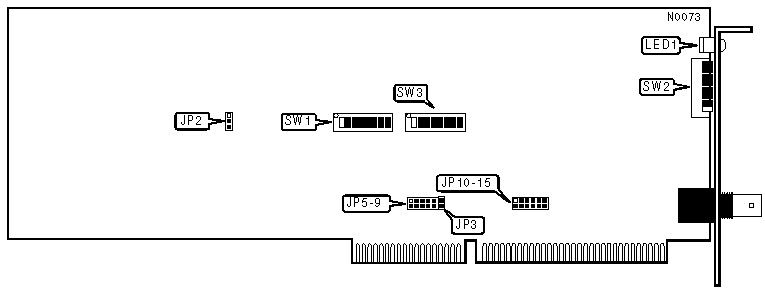
TC3045-CX
|
NIC Type |
TCNS (proprietary) |
|
Transfer Rate |
100Mbps |
|
Data Bus |
16-bit ISA |
|
Topology |
Star |
|
Wiring Type |
RG62A\U 93ohm coaxial |
|
Boot ROM |
Not Available |
|
NODE ADDRESS | ||||||||
|
Node |
SW2/1 |
SW2/2 |
SW2/3 |
SW2/4 |
SW2/5 |
SW2/6 |
SW2/7 |
SW2/8 |
|
0 |
- |
- |
- |
- |
- |
- |
- |
- |
|
1 |
Off |
On |
On |
On |
On |
On |
On |
On |
|
2 |
On |
Off |
On |
On |
On |
On |
On |
On |
|
3 |
Off |
Off |
On |
On |
On |
On |
On |
On |
|
4 |
On |
On |
Off |
On |
On |
On |
On |
On |
|
251 |
Off |
Off |
On |
Off |
Off |
Off |
Off |
Off |
|
252 |
On |
On |
Off |
Off |
Off |
Off |
Off |
Off |
|
253 |
Off |
On |
Off |
Off |
Off |
Off |
Off |
Off |
|
254 |
On |
Off |
Off |
Off |
Off |
Off |
Off |
Off |
|
255 |
Off |
Off |
Off |
Off |
Off |
Off |
Off |
Off |
|
Notes: Node address 0 is used for messaging between nodes and must not be used. A total of 255 node address settings are available. The switches are a binary representation of the decimal node addresses. Switch 1 is the Least Significant Bit and switch 8 is the Most Significant Bit. The switches have the following decimal values: switch 1=1, 2=2, 3=4, 4=8, 5=16, 6=32, 7=64, 8=128. Turn off the switches and add the values of the off switches to obtain the correct node address. (On=0, off=1) | ||||||||
|
BLOCK DECODE | ||
|
Size |
JP2 | |
| » |
16KB |
Pins 1 & 2 Closed |
|
128KB |
Pins 2 & 3 Closed | |
|
Note:A 16-bit VGA adapter typically decodes base memory in 128KB blocks. If you are installing the NIC in a system with such a card, you may need to set the NIC block decode size to 128KB. If you set the block decode size to 128KB then all other adapters in the system must also utilize 128KB decode.
| ||
|
WAIT STATE | ||
|
Setting |
JP3 | |
| » |
Zero wait states enabled |
On |
|
Zero wait states disabled |
Off | |
|
INTERRUPT REQUEST | ||||||||||||
|
IRQ |
JP5 |
JP6 |
JP7 |
JP8 |
JP9 |
JP10 |
JP11 |
JP12 |
JP13 |
JP14 |
JP15 | |
| » |
2 |
Open |
Open |
Open |
Open |
Open |
Open |
Open |
Open |
Open |
Open |
Closed |
|
3 |
Open |
Open |
Open |
Open |
Open |
Closed |
Open |
Open |
Open |
Open |
Open | |
|
4 |
Open |
Open |
Open |
Open |
Open |
Open |
Closed |
Open |
Open |
Open |
Open | |
|
5 |
Open |
Open |
Open |
Open |
Open |
Open |
Open |
Closed |
Open |
Open |
Open | |
|
6 |
Open |
Open |
Open |
Open |
Open |
Open |
Open |
Open |
Closed |
Open |
Open | |
|
7 |
Open |
Open |
Open |
Open |
Open |
Open |
Open |
Open |
Open |
Closed |
Open | |
|
10 |
Open |
Open |
Open |
Open |
Closed |
Open |
Open |
Open |
Open |
Open |
Open | |
|
11 |
Open |
Open |
Open |
Closed |
Open |
Open |
Open |
Open |
Open |
Open |
Open | |
|
12 |
Open |
Open |
Closed |
Open |
Open |
Open |
Open |
Open |
Open |
Open |
Open | |
|
14 |
Closed |
Open |
Open |
Open |
Open |
Open |
Open |
Open |
Open |
Open |
Open | |
|
15 |
Open |
Closed |
Open |
Open |
Open |
Open |
Open |
Open |
Open |
Open |
Open | |
|
BASE MEMORY ADDRESS | |||||||
|
Address |
SW1/1 |
SW1/2 |
SW1/3 |
SW1/4 |
SW1/5 |
SW1/6 | |
|
C000h |
Off |
Off |
On |
On |
On |
On | |
|
C400h |
Off |
Off |
On |
On |
On |
Off | |
|
C800h |
Off |
Off |
On |
On |
On |
On | |
|
CC00h |
Off |
Off |
On |
On |
Off |
Off | |
| » |
D000h |
Off |
Off |
On |
Off |
On |
On |
|
D400h |
Off |
Off |
On |
Off |
On |
On | |
|
D800h |
Off |
Off |
On |
Off |
Off |
On | |
|
DC00h |
Off |
Off |
On |
Off |
Off |
Off | |
|
Note: SW1/7 & SW1/8 are always in the on position. | |||||||
|
I/O BASE ADDRESS | |||||||
|
Address |
SW3/1 |
SW3/2 |
SW3/3 |
SW3/4 |
SW3/5 |
SW3/6 | |
| » |
2E0h |
Off |
On |
Off |
Off |
Off |
On |
|
2F0h |
Off |
On |
Off |
Off |
Off |
Off | |
|
300h |
Off |
Off |
On |
On |
On |
On | |
|
310h |
Off |
Off |
On |
On |
On |
Off | |
|
320h |
Off |
Off |
On |
On |
Off |
On | |
|
330h |
Off |
Off |
On |
On |
Off |
Off | |
|
340h |
Off |
Off |
On |
Off |
On |
On | |
|
350h |
Off |
Off |
On |
Off |
On |
Off | |
|
360h |
Off |
Off |
On |
Off |
Off |
On | |
|
370h |
Off |
Off |
On |
Off |
Off |
Off | |
|
380h |
Off |
Off |
Off |
On |
On |
On | |
|
390h |
Off |
Off |
Off |
On |
On |
Off | |
|
3A0h |
Off |
Off |
Off |
On |
Off |
On | |
|
3B0h |
Off |
Off |
Off |
On |
Off |
Off | |
|
3C0h |
Off |
Off |
Off |
Off |
On |
On | |
|
3D0h |
Off |
Off |
Off |
Off |
On |
Off | |
|
3E0h |
Off |
Off |
Off |
Off |
Off |
On | |
|
3F0h |
Off |
Off |
Off |
Off |
Off |
Off | |
|
COMPATABILITY MODE | ||
|
Setting |
SW3/7 | |
| » |
Enhanced mode |
On |
|
Compatible mode |
Off | |
|
Note: Enhanced mode optimizes performance and minimizes conflicts of your hardware by using a Thomas-Conrad ARCNET drive. It is also not necessary to set the I/O address. In compatible mode the adapter can use most existing ARCNET drivers.
| ||
|
DIAGNOSTIC LED(S) | |||
|
LED |
Color |
Status |
Condition |
|
LED1 |
Red |
On |
Data is being transmitted or received. |
|
LED1 |
Red |
Off |
Data is not being transmitted or received. |
|
LED1 |
Red |
Blinking |
Network connection is good |
|
LED1 |
Red |
Off |
Network connection is broken |