TEXAS MICRO, INC.
L386SX CPU (REV. B)
|
Device Type |
Single board computer |
|
Processor |
AM386SX/80386SX |
|
Processor Speed |
Unidentified |
|
Chip Set |
Unidentified |
|
Video Chip Set |
Unidentified |
|
Maximum Onboard Memory |
16MB |
|
Maximum Video Memory |
Unidentified |
|
Cache |
64KB |
|
BIOS |
Unidentified |
|
Dimensions |
338mm x 122mm |
|
I/O Options |
Floppy drive interface, IDE interface, parallel port, serial ports (2) |
|
NPU options |
80387SX |
|
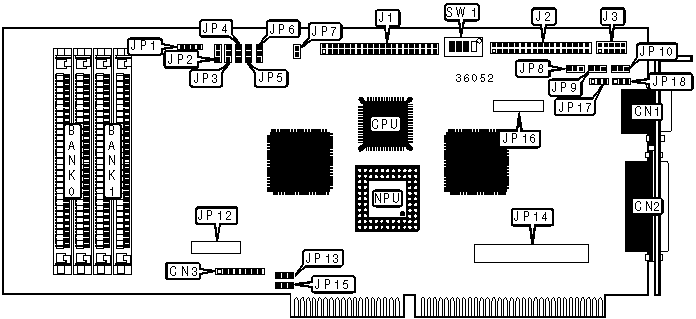
CONNECTIONS |
|||
|
Purpose |
Location |
Purpose |
Location |
|
Serial port 1 |
CN1 |
External battery |
JP1 |
|
Parallel port |
CN2 |
IDE interface LED |
JP7 |
|
Keyboard connector |
CN3 |
Auxiliary keyboard connector |
JP12 |
|
IDE interface |
J1 |
Video board connector |
JP14 |
|
Floppy drive interface |
J2 |
Video board connector |
JP16 |
|
Serial port 2 |
J3 |
|
|
|
USER CONFIGURABLE SETTINGS |
|||
|
Function |
Label |
Position |
|
|
|
On board battery enabled |
JP1 |
Pins 1 & 2 closed |
|
|
On board battery disabled |
JP1 |
Pins 2 & 3 closed |
|
|
Watchdog timer enabled |
JP13 |
Pins 1 & 2 closed |
|
|
Watchdog timer disabled |
JP13 |
Pins 2 & 3 closed |
|
» |
Factory configured - do not alter |
JP17 |
Pins 2 & 3 closed |
|
» |
Factory configured - do not alter |
JP18 |
Pins 2 & 3 closed |
|
» |
Factory configured - do not alter |
JP19 |
Open |
|
» |
Factory configured - do not alter |
JP20 |
Pins 1 & 2 closed |
|
» |
Factory configured - do not alter |
JP21 |
Pins 1 & 2 closed |
|
» |
Monitor type select color |
SW1/1 |
On |
|
|
Monitor type select monochrome |
SW1/1 |
Off |
|
|
Flash memory enabled |
SW1/2 |
Off |
|
|
Flash memory disabled |
SW1/2 |
On |
|
» |
CMOS memory normal operation |
SW1/3 |
Off |
|
|
CMOS memory clear |
SW1/3 |
On |
|
|
I/O address select 270H |
SW1/4 |
Off |
|
|
I/O address select 370H |
SW1/4 |
On |
|
Note: The location of JP19, JP20 & JP21 are unidentified. |
|||
|
SIMM CONFIGURATION |
||
|
Size |
Bank 0 |
Bank 1 |
|
1MB |
(2) 256K x 9 |
(2) 256K x 9 |
|
2MB |
(2) 1M x 9 |
None |
|
4MB |
(2) 1M x 9 |
(2) 1M x 9 |
|
8MB |
(2) 4M x 9 |
None |
|
16MB |
(2) 4M x 9 |
(2) 4M x 9 |
|
CACHE CONFIGURATION |
|
Note: The location of the cache is unidentified. |
|
CACHE JUMPER CONFIGURATION |
|||||
|
Size |
JP2 |
JP3 |
JP4 |
JP5 |
JP6 |
|
64KB |
1 & 2 |
1 & 2 |
1 & 2 |
1 & 2 |
1 & 2 |
|
VIDEO MEMORY CONFIGURATION |
|
Note: The location of the video memory is unidentified. |
|
SERIAL PORT SELECTION |
||||
|
Setting |
JP8 |
JP9 |
JP10 |
|
|
» |
RS-232 |
Pins 2 & 3 closed |
Pins 2 & 3 closed |
Pins 2 & 3 closed |
|
|
RS-422 |
Pins 1 & 2 closed |
Pins 1 & 2 closed |
Pins 1 & 2 closed |
|
|
RS-485 |
Pins 1 & 2 closed |
Pins 1 & 2 closed |
Pins 1 & 2 closed |
|
WATCHDOG SELECTION |
|
|
Seconds |
JP15 |
|
» 1.2 seconds |
Pins 1 & 2 closed |
|
150ms |
Pins 2 & 3 closed |
|
600ms |
Open |