EVEREX SYSTEMS, INC.
STEP MP EV-2607
|
Processor |
80386DX/80486DX (Depending on which CPU card is used) |
|
Processor Speed |
25/33MHz |
|
Chip Set |
C & T |
|
Max. Onboard DRAM |
64MB |
|
SRAM Cache |
64/256KB |
|
BIOS |
Quadtel |
|
Dimensions |
330mm x 220mm |
|
I/O Options |
Base card slots (3), CPU Card slot, external memory card, SCSI card slots (2) |
|
NPU Options |
80387DX (Depending on which CPU card is used) |
|
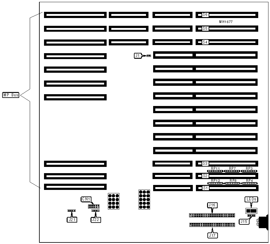
CONNECTIONS | |||
|
Purpose |
Location |
Purpose |
Location |
|
LED display |
CN1 |
Speaker |
J22 |
|
Chassis fan power |
J15 |
Power good LEDs |
LEDs |
|
SCSI B connector |
J16 |
16-bit external memory card |
S1 |
|
SCSI A connector |
J17 |
SCSI board slots |
S2 & S3 |
|
Chassis fan power |
J21 |
Base card slots |
S4, S5, & S6 |
|
USER CONFIGURABLE SETTINGS | |||
|
Function |
Jumper |
Position | |
| » |
I/O bus select ISA card set |
J1 |
closed |
|
I/O bus select EISA card set |
J1 |
open | |
|
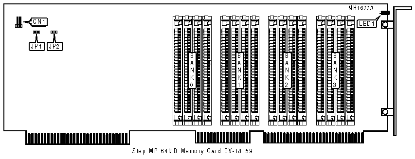
CONNECTIONS | |||
|
Purpose |
Location |
Purpose |
Location |
|
Memory activity indicator |
CN1 |
ECC fault indicator LED |
LED1 |
|
DRAM CONFIGURATION | ||||
|
Size |
Bank 0 |
Bank 1 |
Bank 2 |
Bank 3 |
|
16MB |
(4) 4M x 9 |
NONE |
NONE |
NONE |
|
32MB |
(4) 4M x 9 |
(4) 4M x 9 |
NONE |
NONE |
|
48MB |
(4) 4M x 9 |
(4) 4M x 9 |
(4) 4M x 9 |
NONE |
|
64MB |
(4) 4M x 9 |
(4) 4M x 9 |
(4) 4M x 9 |
(4) 4M x 9 |
|
NOTE |
|
Note:This card must be place in either slot 5 or 6 on the system board only. If installing the card in slot 5 then resistors RP4, RP8, & RP12 must be removed. If installing the card in slot 6 then |
|
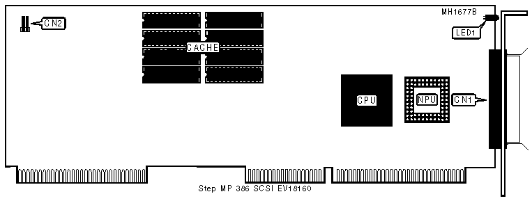
CONNECTIONS | |||
|
Purpose |
Location |
Purpose |
Location |
|
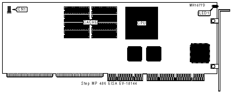
CPU activity indicator connector |
CN1 |
CPU activity indicator LED |
LED1 |
|
SCSI connector |
CN2 | ||
|
CACHE CONFIGURATION | |
|
Size |
Cache |
|
64KB |
(8) 8K x 8 |
|
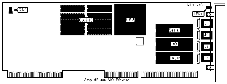
CONNECTIONS | |||
|
Purpose |
Location |
Purpose |
Location |
|
CPU activity indicator connector |
CN1 |
RS422 Serial I/O connector |
J3 |
|
RS422 Serial I/O connector |
J1 |
RS422 Serial I/O connector |
J4 |
|
RS422 Serial I/O connector |
J2 |
CPU activity indicator LED |
LED1 |
|
CACHE CONFIGURATION | |
|
Size |
Cache |
|
256KB |
(8) 256K x 1 |
|
CONNECTIONS | |||
|
Purpose |
Location |
Purpose |
Location |
|
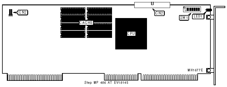
CPU activity indicator connector |
CN1 |
CPU activity indicator LED |
LED1 |
|
CACHE CONFIGURATION | |
|
Size |
Cache |
|
256KB |
(8) 256K x 1 |
|
MEMORY ADDRESS CONFIGURATION | |||||||
|
Function |
SW1/1 |
SW1/2 |
SW1/3 |
SW1/4 |
SW1/5 |
SW1/6 |
SW1/7 |
|
Disable 8th MB |
On |
Off |
Off |
Off |
Off |
Off |
Off |
|
Disable 9th MB |
Off |
On |
Off |
Off |
Off |
Off |
Off |
|
Disable 10th MB |
Off |
Off |
On |
Off |
Off |
Off |
Off |
|
Disable 11th MB |
Off |
Off |
Off |
On |
Off |
Off |
Off |
|
Disable 12th MB |
Off |
Off |
Off |
Off |
On |
Off |
Off |
|
Disable 13th MB |
Off |
Off |
Off |
Off |
Off |
On |
Off |
|
Disable 14th MB |
Off |
Off |
Off |
Off |
Off |
Off |
On |
|
Note:Turning on one or more of the above switches will open a window of addressed space for configuration of memory mappd devices like network controllers and multiport cards. | |||||||
|
CONNECTIONS | |||
|
Purpose |
Location |
Purpose |
Location |
|
CPU activity indicator connector |
CN1 |
CPU activity indicator LED |
LED1 |
|
Base CPU Ribbon connector |
CN2 | ||
|
CACHE CONFIGURATION | |
|
Size |
Cache |
|
256KB |
(8) 256K x 1 |

|
CONNECTIONS | |||
|
Purpose |
Location |
Purpose |
Location |
|
Parallel port |
CN1 |
SCSI connector |
CN4 |
|
Serial port |
CN2 |
Reset button |
CN5 |
|
Paddle port connector (optional) |
CN3 |
Floppy drive interface |
CN6 |

|
CONNECTIONS | |||
|
Purpose |
Location |
Purpose |
Location |
|
Serial port |
CN1 |
Floppy drive interface |
CN3 |
|
Base CPU ribbon connector |
CN2 |
Reset switch |
CN4 |
|
USER CONFIGURABLE SETTINGS | |||
|
Function |
Jumper |
Position | |
| » |
Montior type select color |
J1 |
Open |
|
Monitor type select monochrome |
J1 |
Closed | |
| » |
Floppy drive interface enabled |
J2 |
Open |
|
Floppy drive interface disabled |
J2 |
Closed | |
| » |
Serial port select COM1 |
J3 |
Open |
|
Serial port select COM2 |
J3 |
Closed | |
| » |
Factory configured - do not alter |
J4 |
Open |