AST RESEARCH, INC.
PREMMIA SYSTEM BOARD (P/N202514-00X)
|
Processor |
80486SX/80487SX/80486DX/ODP486SX/80486DX2/Pentium |
|
Processor Speed |
25/33/50(internal)/66(internal)MHz |
|
Chip Set |
ATI |
|
Max. Onboard DRAM |
128MB |
|
Cache |
64/256KB (Located on the external cache module) |
|
BIOS |
AST |
|
Dimensions |
355mm x 304mm |
|
I/O Options |
Cache/Pentium upgrade module, floppy drive interface (2), IDE interface, parallel port, PS/2 mouse port, serial ports (2), VGA feature connector, video port |
|
NPU Options |
None |
|
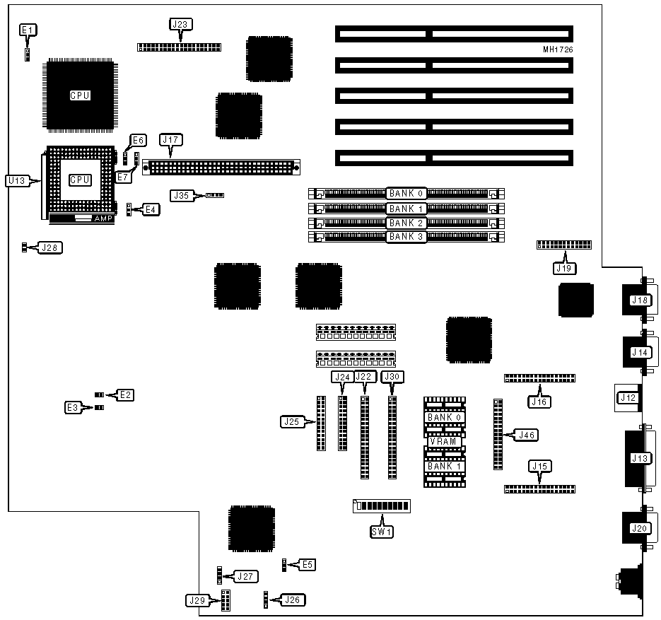
CONNECTIONS | |||
|
Purpose |
Location |
Purpose |
Location |
|
Bus mouse port |
J12 |
Manufacturer’s test header |
J23 |
|
Parallel port |
J13 |
Floppy drive interface 1 & 2 |
J24 |
|
Serial port 1 |
J14 |
Floppy drive interface 3 |
J25 |
|
Personality/feature connector |
J15 |
External battery |
J26 |
|
Personality/feature connector |
J16 |
Speaker |
J27 |
|
Pentium/Cache module upgrade |
J17 |
Chassis fan power |
J28 |
|
SVGA monitor port |
J18 |
Front console header |
J29 |
|
VGA port |
J19 |
Manufacturer’s test header |
J30 |
|
Serial port 2 |
J20 |
IDE interface LED |
J35 |
|
IDE interface |
J22 |
Personality/feature connector |
J46 |
|
Note:The personality/feature connectors alow various network modules to be added to the system. | |||
|
USER CONFIGURABLE SETTINGS | |||
|
Function |
Jumper/Switch |
Position | |
|
» |
Factory configured - do not alter |
E2 |
Open |
|
» |
Pariity checking enabled |
E3 |
Closed |
|
Pariity checking disabled |
E3 |
Open | |
|
» |
Flash BIOS voltage 12V |
E5 |
pins 2 & 3 closed |
|
Flash BIOS voltage 5V |
E5 |
pins 1 & 2 open | |
|
» |
VGA enabled |
SW1/switch 1 |
On |
|
VGA disabled |
SW1/switch 1 |
Off | |
|
» |
Factory configured - do not alter |
SW1/switch 2 |
N/A |
|
» |
CMOS memory normal operation |
SW1/switch 3 |
Off |
|
CMOS memory clear |
SW1/switch 3 |
On | |
|
» |
BIOS normal operation |
SW1/switch 4 |
Off |
|
BIOS forced update |
SW1/switch 4 |
On | |
|
» |
Password override |
SW1/switch 5 |
Off |
|
Password inhibited |
SW1/switch 5 |
On | |
|
» |
Factory configured - do not alter |
SW1/switch 6 |
Off |
|
» |
Factory configured - do not alter |
SW1/switch 7 |
Off |
|
» |
Factory configured - do not alter |
SW1/switch 8 |
Off |
|
» |
Factory configured - do not alter |
SW1/switch 9 |
Off |
|
» |
Monitor type select color |
SW1/switch 10 |
On |
|
Monitor type select monochrome |
SW1/switch 10 |
Off | |
|
DRAM CONFIGURATION | ||||
|
Size |
Bank 0 |
Bank 1 |
Bank 2 |
Bank 3 |
|
2MB |
(1) 1M x 36 |
(1) 1M x 36 |
NONE |
NONE |
|
4MB |
(1) 1M x 36 |
(1) 1M x 36 |
(1) 1M x 36 |
(1) 1M x 36 |
|
4MB |
(1) 2M x 36 |
(1) 2M x 36 |
NONE |
NONE |
|
6MB |
(1) 1M x 36 |
(1) 1M x 36 |
(1) 2M x 36 |
(1) 2M x 36 |
|
8MB |
(1) 2M x 36 |
(1) 2M x 36 |
(1) 2M x 36 |
(1) 2M x 36 |
|
8MB |
(1) 4M x 36 |
(1) 4M x 36 |
NONE |
NONE |
|
10MB |
(1) 1M x 36 |
(1) 1M x 36 |
(1) 4M x 36 |
(1) 4M x 36 |
|
12MB |
(1) 2M x 36 |
(1) 2M x 36 |
(1) 4M x 36 |
(1) 4M x 36 |
|
16MB |
(1) 4M x 36 |
(1) 4M x 36 |
(1) 4M x 36 |
(1) 4M x 36 |
|
16MB |
(1) 8M x 36 |
(1) 8M x 36 |
NONE |
NONE |
|
18MB |
(1) 1M x 36 |
(1) 1M x 36 |
(1) 8M x 36 |
(1) 8M x 36 |
|
20MB |
(1) 2M x 36 |
(1) 2M x 36 |
(1) 8M x 36 |
(1) 8M x 36 |
|
24MB |
(1) 4M x 36 |
(1) 4M x 36 |
(1) 8M x 36 |
(1) 8M x 36 |
|
32MB |
(1) 8M x 36 |
(1) 8M x 36 |
(1) 8M x 36 |
(1) 8M x 36 |
|
32MB |
(1) 16M x 36 |
(1) 16M x 9 |
NONE |
NONE |
|
34MB |
(1) 1M x 36 |
(1) 1M x 36 |
(1) 16M x 36 |
(1) 16M x 36 |
|
36MB |
(1) 2M x 36 |
(1) 2M x 36 |
(1) 16M x 36 |
(1) 16M x 36 |
|
40MB |
(1) 4M x 36 |
(1) 4M x 36 |
(1) 16M x 36 |
(1) 16M x 36 |
|
48MB |
(1) 8M x 36 |
(1) 8M x 36 |
(1) 16M x 36 |
(1) 16M x 36 |
|
64MB |
(1) 16M x 36 |
(1) 16M x 36 |
(1) 16M x 36 |
(1) 16M x 36 |
|
64MB |
(1) 32M x 36 |
(1) 32M x 36 |
NONE |
NONE |
|
66MB |
(1) 1M x 36 |
(1) 1M x 36 |
(1) 32M x 36 |
(1) 32M x 36 |
|
68MB |
(1) 2M x 36 |
(1) 2M x 36 |
(1) 32M x 36 |
(1) 32M x 36 |
|
72MB |
(1) 4M x 36 |
(1) 4M x 36 |
(1) 32M x 36 |
(1) 32M x 36 |
|
80MB |
(1) 8M x 36 |
(1) 8M x 36 |
(1) 32M x 36 |
(1) 32M x 36 |
|
96MB |
(1) 16M x 36 |
(1) 16M x 36 |
(1) 32M x 36 |
(1) 32M x 36 |
|
128MB |
(1) 32M x 36 |
(1) 32M x 36 |
(1) 32M x 36 |
(1) 32M x 36 |
|
CPU TYPE CONFIGURATION | ||||||
|
PQFP |
PGA |
Pentium |
E1 |
E4 |
E6 |
E7 |
|
80486SX |
None |
None |
pins 2 & 3 |
pins 1 & 2 |
pins 1 & 2 |
pins 1 & 2 |
|
80486SX |
80487SX |
None |
pins 2 & 3 |
pins 1 & 2 |
pins 1 & 2 |
pins 1 & 2 |
|
80486SX |
ODP486SX |
None |
pins 2 & 3 |
pins 1 & 2 |
pins 1 & 2 |
pins 1 & 2 |
|
80486SX |
80486DX/80486DX2 |
None |
pins 1 & 2 |
pins 2 & 3 |
pins 1 & 2 |
pins 1 & 2 |
|
80486DX |
None |
None |
pins 2 & 3 |
pins 1 & 2 |
pins 1 & 2 |
pins 1 & 2 |
|
80486DX |
80486DX/80486DX2 |
None |
pins 1 & 2 |
pins 2 & 3 |
pins 1 & 2 |
pins 1 & 2 |
|
80486DX |
ODP486SX |
None |
pins 2 & 3 |
pins 1 & 2 |
pins 1 & 2 |
pins 1 & 2 |
|
None |
80486SX |
None |
Open |
Open |
pins 2 & 3 |
pins 2 & 3 |
|
None |
80486DX/80486DX2 |
None |
Open |
pins 2 & 3 |
pins 1 & 2 |
pins 1 & 2 |
|
None |
ODP486SX |
None |
Open |
pins 1 & 2 |
pins 1 & 2 |
pins 1 & 2 |
|
Any |
None |
Yes |
pins 2 & 3 |
pins 1 & 2 |
pins 1 & 2 |
pins 1 & 2 |
|
None |
None |
Yes |
Open |
pins 1 & 2 |
pins 1 & 2 |
pins 1 & 2 |
|
Note:Pins designated should be in the closed position. Before installing the Pentium upgrade board, remove the processor in the ZIF socket at U13. | ||||||
|
VIDEO MEMORY CONFIGURATION | ||
|
Size |
Bank 0 |
Bank 1 |
|
1MB |
(2) 46256 |
(2) 46256 |
|
2MB |
(2) 46256 |
(2) 46256 |