EMULEX CORPORATION
TIME-SPECTRUM MULTIFUNCTION BOARD
|
Card Type |
Multi-I/O |
|
Chipset |
Unidentified |
|
Maximum Onboard Memory |
256KB DRAM |
|
I/O Options |
Clock/calendar, parallel port, serial port |
|
Data Bus |
8-bit ISA |
|
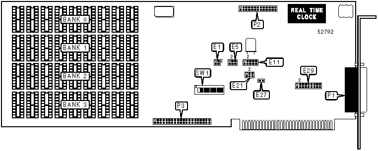
CONNECTIONS | |||
|
Function |
Label |
Function |
Label |
|
Serial port |
P1 |
Unidentified |
P3 |
|
Parallel port |
P2 | ||
|
Note:P1, P2, and the real-time clock are optional and may not be installed on all boards. | |||
|
USER CONFIGURABLE SETTINGS | |||
|
Setting |
Label |
Position | |
| » |
Factory configured - do not alter |
E1 |
Pins 1 & 3 closed |
| » |
High hysteresis serial port mode disabled |
E27 |
Open |
|
High hysteresis serial port mode enabled |
E27 |
Closed | |
|
Clock/calendar address is 350h |
SW1/7 |
On | |
|
Clock/calendar address is 250h |
SW1/7 |
Off | |
|
Parallel port address is 378h |
SW1/8 |
On | |
|
Parallel port address is 278h |
SW1/8 |
Off | |
|
SERIAL PORT ADDRESS SELECTION | ||
|
Setting |
SW1/5 |
SW1/6 |
|
3F8h (COM1:) |
On |
Off |
|
2F8h (COM2:) |
Off |
On |
|
Disabled |
On |
On |
|
CLOCK/CALENDAR INTERRUPT SELECTION | |
|
Setting |
E21 |
|
IRQ2 |
Pins 4 & 5 closed |
|
IRQ3 |
Pins 1 & 2 closed |
|
IRQ4 |
Pins 2 & 3 closed |
|
IRQ5 |
Pins 5 & 6 closed |
|
None |
Open |
|
SERIAL PORT INTERRUPT SELECTION | ||
|
Setting |
E11 | |
|
IRQ2 |
Pins 6 & 7 closed | |
|
IRQ3 |
Pins 1 & 2 closed | |
| » |
IRQ4 |
Pins 2 & 3 closed |
|
IRQ5 |
Pins 7 & 8 closed | |
|
PARALLEL PORT INTERRUPT SELECTION | ||
|
Setting |
E5 | |
|
IRQ2 |
Pins 5 & 6 closed | |
|
IRQ3 |
Pins 2 & 3 closed | |
|
IRQ5 |
Pins 1 & 2 closed | |
| » |
IRQ7 |
Pins 4 & 5 closed |
|
STARTING MEMORY ADDRESS SELECTION | ||||
|
Setting |
SW1/1 |
SW1/2 |
SW1/3 |
SW1/4 |
|
64KB |
Off |
Off |
Off |
Off |
|
128KB |
On |
Off |
Off |
Off |
|
192KB |
Off |
On |
Off |
Off |
|
256KB |
On |
On |
Off |
Off |
|
320KB |
Off |
Off |
On |
Off |
|
384KB |
On |
Off |
On |
Off |
|
448KB |
Off |
On |
On |
Off |
|
512KB |
On |
On |
On |
Off |
|
576KB |
Off |
Off |
Off |
On |
|
640KB |
On |
Off |
Off |
On |
|
704KB |
Off |
On |
Off |
On |
|
768KB |
Off |
Off |
On |
On |
|
SERIAL PORT CONFIGURATION | |
|
Setting |
E29 |
|
Normal configuration |
Pins 1 & 10, 2 & 11, 3 & 12, 4 & 13, 5 & 14, 6 & 15 closed |
|
2- or 3-wire, transmit/receive normal |
Pins 1 & 10, 2 & 11, 7 & 16, 8 & 17, 9 & 18 closed |
|
2- or 3-wire, transmit/receive reversed |
Pins 1 & 2, 7 & 16, 8 & 17, 9 & 18, 10 & 11 closed |
|
Serial printer configuration, CTS input from READY and CTS |
Pins 1 & 10, 4 & 13, 8 & 17, 9 & 18 closed |
|
Serial printer configuration, CTS input from READY only |
Pins 1 & 10, 8 & 17, 9 & 18 closed |
|
DRAM CONFIGURATION | ||||
|
Setting |
Bank 0 |
Bank 1 |
Bank 2 |
Bank 3 |
|
0KB |
None |
None |
None |
None |
|
64KB |
(9) 64K x 1 |
None |
None |
None |
|
128KB |
(9) 64K x 1 |
(9) 64K x 1 |
None |
None |
|
192KB |
(9) 64K x 1 |
(9) 64K x 1 |
(9) 64K x 1 |
None |
|
256KB |
(9) 64K x 1 |
(9) 64K x 1 |
(9) 64K x 1 |
(9) 64K x 1 |