SILICON VALLEY COMPUTER INC.
ADP111V
|
| |
|
Data bus: |
32-bit, VL-bus |
|
Size: |
Full-length, full-height card |
|
Hard drive supported: |
(2) IDE(AT) interface drives, (2) IDE mirror drives, IDE tape drive |
|
Floppy drives supported: |
360KB, 720KB, 1.2MB, or 1.44MB drives |
|
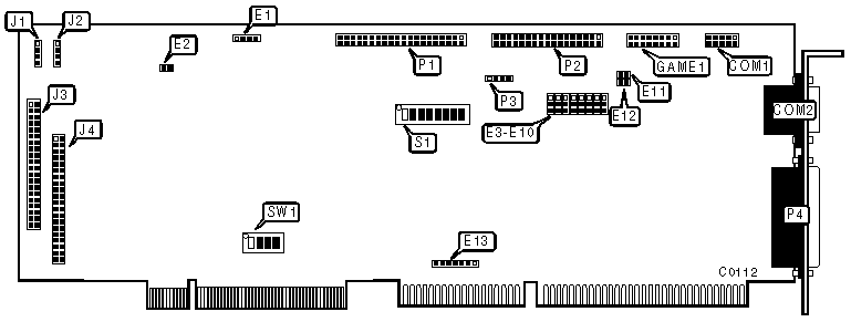
CONNECTIONS | |
|
Function |
Location |
|
9-pin serial port 1 - internal |
COM1 |
|
9-pin serial port 2 - external |
COM2 |
|
15-pin connector - game port |
GAME1 |
|
4-pin connector - Mirror drive active LED |
J1 |
|
4-pin connector - primary drive active LED |
J2 |
|
40-pin connector - IDE mirror drive cable |
J3 |
|
40-pin IDE(AT) interface connector |
J4 |
|
40-pin ISA IDE tape/IDE CD-ROM interface connector |
P1 |
|
34-pin control cable connector - floppy drive |
P2 |
|
4-pin connector - IDE tape/IDE CD-ROM drive active LED |
P3 |
|
25-pin parallel port - external |
P4 |
|
USER CONFIGURABLE SETTINGS | |||
|
Function |
Location |
Setting | |
|
8051/8031 micro controller is installed |
E1 |
pins 1 & 2, 3 & 4 closed | |
|
80C51/80C31 micro controller is installed |
E1 |
pins 2 & 3 closed | |
| » |
Serial port 2 enabled |
E3 |
pins 2 & 3 closed |
|
Serial port 2 disabled |
E3 |
pins 1 & 2 closed | |
| » |
Parallel port enabled |
E4 |
pins 2 & 3 closed |
|
Parallel port disabled |
E4 |
pins 1 & 2 closed | |
|
USER CONFIGURABLE SETTINGS(CONTINUED) | |||
|
Function |
Location |
Setting | |
| » |
ISA IDE interface enabled |
E5 |
pins 2 & 3 closed |
|
ISA IDE interface disabled |
E5 |
pins 1 & 2 closed | |
| » |
Floppy drive interface enabled |
E6 |
pins 2 & 3 closed |
|
Floppy drive interface disabled |
E6 |
pins 1 & 2 closed | |
| » |
Serial port 2 address 2F8 - 2EFh select |
E7 |
pins 2 & 3 closed |
|
Serial port 2 address 2E8 - 2EFh select |
E7 |
pins 1 & 2 closed | |
| » |
Serial port 1 address 3F8 - 3FFh select |
E8 |
pins 2 & 3 closed |
|
Serial port 1 address 3E8 - 3EFh select |
E8 |
pins 1 & 2 closed | |
| » |
Serial port 1 enabled |
E9 |
pins 2 & 3 closed |
|
Serial port 1 disabled |
E9 |
pins 1 & 2 closed | |
| » |
Parallel port address 378 - 37Fh select |
E10 |
pins 2 & 3 closed |
|
Parallel port address 278 - 27Fh select |
E10 |
pins 1 & 2 closed | |
| » |
Game port enabled |
E11 & E12 |
closed |
|
Game port disabled |
E11 & E12 |
open | |
| » |
ISA IDE tape drive interrupt IRQ15 select |
E13 |
pins 2 & 3 closed |
|
ISA IDE tape drive interrupt IRQ10 select |
E13 |
pins 1 & 2 closed | |
|
ISA IDE tape drive interrupt IRQ14 select(do not use) |
E13 |
pins 4 & 5 closed | |
| » |
VESA IDE interface interrupt IRQ14 select |
E13 |
pins 5 & 6 closed |
|
VESA IDE interface interrupt IRQ15 select(do not use) |
E13 |
pins 6 & 7 closed | |
|
Factory configured - do not alter |
S1/4 |
N/A | |
|
Factory configured - do not alter |
S1/5 |
N/A | |
| » |
External BIOS enabled |
S1/6 |
off |
|
Internal BIOS enabled |
S1/6 |
on | |
| » |
Factory configured - do not alter |
S1/7 |
N/A |
| » |
Factory configured - do not alter |
S1/8 |
N/A |
| » |
Factory configured - do not alter |
SW1/4 |
on |
|
BASE MEMORY ADDRESS SELECT | |||
|
Address |
S1/1 |
S1/2 | |
| » |
CC000h |
on |
off |
|
D8000h |
off |
on | |
|
DC000h |
off |
off | |
|
Disabled |
on |
on | |
|
BIOS SIZE | |||
|
Size |
E2 |
S1/3 | |
| » |
8KB |
open |
on |
|
16KB |
closed |
off | |
|
Note: The manufacturer recommends that the default value of 8KB should not be changed by the user. | |||
|
DATA TRANSFER RATE TABLE | |||
|
CPU Speed/Type | |||
|
Setting |
25/DX2-50 MHz |
33/DX-66 MHz |
50MHz |
|
0 |
1.67 |
2.22 |
3.33 |
|
1 |
2.00 |
2.66 |
4.00 |
|
2 |
2.50 |
3.33 |
5.00 |
|
3 |
2.94 |
3.92 |
5.88 |
|
4 |
3.12 |
4.60 |
6.25 |
|
5 |
4.16 |
5.55 |
8.33 |
|
6 |
4.54 |
6.06 |
9.09 |
|
7 |
6.25 |
8.33 |
12.50 |
|
DATA TRANSFER RATE SWITCH SETTINGS | |||
|
Setting |
SW1/1 |
SW1/2 |
SW1/3 |
|
0 |
on |
on |
on |
|
1 |
on |
on |
off |
|
2 |
on |
off |
on |
|
3 |
on |
off |
off |
|
4 |
off |
on |
on |
|
5 |
off |
on |
off |
|
6 |
off |
off |
on |
|
7 |
off |
off |
off |