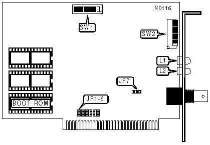
TIARA COMPUTER SYSTEMS, INC.
LanCard/A * PC & LanCard/A * PC HiZ
|
NIC Type |
ARCnet |
|
Transfer Rate |
2.5Mbps |
|
Data Bus |
8-bit ISA |
|
Topology |
Star (PC) Linear Bus (PC HiZ) |
|
Wiring Type |
RG-62A/U 93ohm coaxial (PC and PC HiZ) RG-58A/U 50ohm coaxial (HiZ only) |
|
Boot ROM |
Available |
|
NODE ADDRESS |
||||||||
|
Node |
SW2/1 |
SW2/2 |
SW2/3 |
SW2/4 |
SW2/5 |
SW2/6 |
SW2/7 |
SW2/8 |
|
0 |
- |
- |
- |
- |
- |
- |
- |
- |
|
1 |
Off |
Off |
Off |
Off |
Off |
Off |
Off |
On |
|
2 |
Off |
Off |
Off |
Off |
Off |
Off |
On |
Off |
|
3 |
Off |
Off |
Off |
Off |
Off |
Off |
On |
On |
|
4 |
Off |
Off |
Off |
Off |
Off |
On |
Off |
Off |
|
251 |
On |
On |
On |
On |
On |
Off |
On |
On |
|
252 |
On |
On |
On |
On |
On |
On |
Off |
Off |
|
253 |
On |
On |
On |
On |
On |
On |
Off |
On |
|
254 |
On |
On |
On |
On |
On |
On |
On |
Off |
|
255 |
On |
On |
On |
On |
On |
On |
On |
On |
|
Note: Node address 0 is used for messaging between nodes and must not be used. A total of 255 node address settings are available. The switches are a binary representation of the decimal node addresses. Switch 8 is the Least Significant Bit and switch 1 is the Most Significant Bit. The switches have the following decimal values: switch 8=1, 7=2, 6=4, 5=8, 4=16, 3=32, 2=64, 1=128. Turn on the switches and add the values of the on switches to obtain the correct node address. (On=1, Off=0) |
||||||||
|
INTERRUPT REQUEST |
||||||
|
IRQ |
JP1 |
JP2 |
JP3 |
JP4 |
JP5 |
JP6 |
|
2 |
Closed |
Open |
Open |
Open |
Open |
Open |
|
3 |
Open |
Closed |
Open |
Open |
Open |
Open |
|
4 |
Open |
Open |
Closed |
Open |
Open |
Open |
|
5 |
Open |
Open |
Open |
Closed |
Open |
Open |
|
6 |
Open |
Open |
Open |
Open |
Closed |
Open |
|
7 |
Open |
Open |
Open |
Open |
Open |
Closed |
|
ENHANCED DIAGNOSTICS ENABLE |
||
|
Setting |
JP7 |
|
|
» |
Disabled |
Pins 1 & 2 closed |
|
|
Enabled |
Pins 2 & 3 closed |
|
Note: The enhanced diagnostics are compatible only with the driver that was shipped with this card. |
||
|
I/O BASE ADDRESS |
||||
|
Address |
SW1/1 |
SW1/2 |
SW1/3 |
|
|
» |
2E0h |
Off |
On |
Off |
|
|
260h |
Off |
Off |
Off |
|
|
290h |
Off |
Off |
On |
|
|
2B0h |
Off |
On |
On |
|
|
300h |
On |
Off |
Off |
|
|
350h |
On |
Off |
On |
|
|
380h |
On |
On |
On |
|
|
3E0h |
On |
On |
On |
|
RIM BUFFER ADDRESS CONFIGURATION |
||||
|
Buffer Address |
SW1/4 |
SW1/5 |
SW1/6 |
|
|
» |
D0OO-D3FFH |
On |
Off |
Off |
|
|
C0OO-C3FFH |
Off |
Off |
Off |
|
|
C4OO-C7FFH |
Off |
Off |
On |
|
|
CCOO-CFFFH |
Off |
On |
On |
|
|
D4OO-D7FFH |
On |
Off |
On |
|
|
D8OO-DBFFH |
On |
On |
Off |
|
|
DCOO-DFFFH |
On |
On |
On |
|
|
E000-E3FFH |
Off |
On |
Off |
Note: The lower 8K of the address above is used as a network data buffer. The upper 8K is where the Boot ROM is loaded into system memory. |
||||
|
CABLE LENGTH AND RESPONSE/RECONFIGURATION TIMEOUTS |
|||||
|
Maximum Length |
Response Time |
Reconfiguration |
SW1/7 |
SW1/8 |
|
|
» |
4.8 miles |
74.7µs |
840ms |
On |
On |
|
|
21.0 miles |
283.4µs |
1680ms |
On |
Off |
|
|
42.5 miles |
561.8µs |
1680ms |
Off |
On |
|
|
85.6 miles |
1118.6µs |
1680ms |
Off |
Off |
|
Note: Maximum length is the distance between the two farthest cards on the network. All cards on a segment must have this option set the same. |
|||||
|
DIAGNOSTIC LED(S) |
|||
|
LED |
Color |
Status |
Condition |
|
L1 |
Red |
On |
Data is being received |
|
L1 |
Red |
Off |
Data is not being received |
|
L1 |
Red |
Blinking |
Card is reconfiguring |
|
L2 |
Green |
On |
Data is being transmitted |
|
L2 |
Green |
Off |
Data is not being transmitted |
|
L2 |
Green |
Blinking |
Card is reconfiguring |
Note: If LEDs L1 & L2 continue to blink for an extended amount of time, this indicates a network problem such as a defective card, a broken network connection, or a hub failure. |
|||