KATRON TECHNOLOGIES, INC.
EISA 32-BIT MASTER BUS ETHERNET ADAPTER
|
NIC Type |
Ethernet |
|
Transfer Rate |
10Mbps |
|
Data Bus |
32-bit EISA |
|
Topology |
Linear bus |
|
Wiring Type |
Shielded/Unshielded Twisted Pair AUI transceiver via DB-15 port RG-58A/U 50ohm coaxial |
|
Boot ROM |
Available |
|
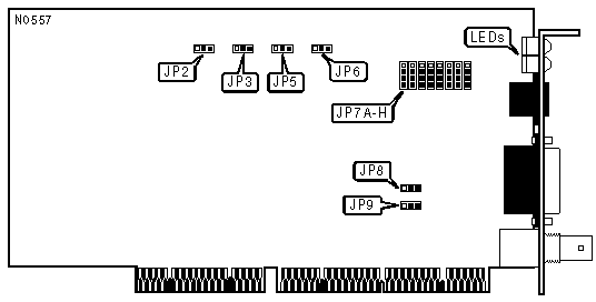
FACTORY CONFIGURED SETTINGS | |
|
Jumper |
Setting |
|
JP2 |
Pins 1 & 2 closed |
|
JP3 |
Pins 2 & 3 closed |
|
NETWORK VERSION | ||
|
Version |
JP5 | |
| » |
Ethernet Version 2 (can use all ports) |
Pins 1 & 2 closed |
|
Ethernet Version 1 (uses AUI port only) |
Pins 2 & 3 closed | |
|
LINK INTEGRITY TEST | ||
|
Setting |
JP6 | |
| » |
Enabled |
Pins 1 & 2 closed |
|
Disabled |
Pins 2 & 3 closed | |
|
Note:The link integrity test is only valid when the cable type is unshielded twisted pair. | ||
|
CABLE TYPE | ||
|
Type |
JP7 | |
|
Shielded/Unshielded Twisted Pair |
Pins 1 & 2 closed | |
|
AUI transceiver via DB-15 port |
Pins 2 & 3 closed | |
| » |
RG-58A/U 50ohm coaxial |
Pins 3 & 4 closed |
|
SEGMENT LENGTH | ||
|
Maximum Length |
JP8 | |
| » |
185 meters |
Pins 1 & 2 closed |
|
300 meters |
Pins 2 & 3 closed | |
|
Note:Segment length is the total length of cable between the two farthest cards on the segment. Each card on the segment must have this option set the same. | ||
|
ONBOARD TERMINATOR | |||
|
Setting |
JP9 | ||
| » |
Disabled |
Pins 1 & 2 closed | |
|
Enabled |
Pins 2 & 3 closed | ||
|
Notes:If the card is on either end of a linear bus network segment, the onboard terminator may be used instead of using an external terminator.
| |||

|
DIAGNOSTIC LED(S) | |||
|
LED |
Color |
Status |
Condition |
|
LED1 |
Green |
On |
Link is correctly configured |
|
LED1 |
Green |
Blinking |
Link is incorrectly configured |
|
LED1 |
Green |
Off |
Twisted pair connection not used/Link test is disabled |
|
LED2 |
Yellow |
On |
Twisted pair polarity is reversed and corrected |
|
LED2 |
Yellow |
Off |
Twisted pair polarity is correct/Twisted pair connection not used |
|
LED3 |
Green |
On |
Card is not powered or has failed |
|
LED3 |
Green |
Blinking |
Data is being transmitted or received |
|
LED3 |
Green |
Off |
Data is not being transmitted or received |
|
LED4 |
Yellow |
On |
Collision detected on network |
|
LED4 |
Yellow |
Off |
No collisions detected on network |