EDIMAX COMPUTER COMPANY
AL-2351
|
NIC Type |
Arcnet |
|
Transfer Rate |
2.5Mbps |
|
Data Bus |
8-bit ISA |
|
Topology |
Linear bus Star |
|
Wiring Type |
Unshielded twisted pair RG-62A/U 93ohm coaxial |
|
Boot ROM |
Available |
|
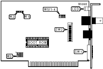
NODE ADDRESS SELECTION |
||||||||
|
Address |
SW1/1 |
SW1/2 |
SW1/3 |
SW1/4 |
SW1/5 |
SW1/6 |
SW1/7 |
SW1/8 |
|
1 |
Off |
On |
On |
On |
On |
On |
On |
On |
|
2 |
On |
Off |
On |
On |
On |
On |
On |
On |
|
3 |
Off |
Off |
On |
On |
On |
On |
On |
On |
|
4 |
On |
On |
Off |
On |
On |
On |
On |
On |
|
5 |
Off |
On |
Off |
On |
On |
On |
On |
On |
|
251 |
Off |
Off |
On |
Off |
Off |
Off |
Off |
Off |
|
252 |
On |
On |
Off |
Off |
Off |
Off |
Off |
Off |
|
253 |
Off |
On |
Off |
Off |
Off |
Off |
Off |
Off |
|
254 |
On |
Off |
Off |
Off |
Off |
Off |
Off |
Off |
|
255 |
Off |
Off |
Off |
Off |
Off |
Off |
Off |
Off |
Note: A total of 255 node address settings are available. The switches are a binary representation of the decimal node addresses. Switch SW1/1 is the Least Significant Bit and switch SW1/8 is the Most Significant Bit. The switches have the following decimal values: jumper SW1/1=1, SW1/2=2, SW1/=4, SW1/4=8, SW1/5=16, SW1/6=32, SW1/7=64, SW1/8=128.Open the switches and add the values of the off switches to obtain the correct node address. (On=0, Off=1) |
||||||||
|
TOPOLOGY |
|||||
|
Topology |
W5/1 |
W5/2 |
W5/3 |
W5/4 |
|
|
Star |
Closed |
Open |
Open |
Open |
|
|
Linear bus |
Open |
Closed |
Open |
Open |
|
|
» |
Linear bus |
Open |
Open |
Closed |
Closed |
|
BASE I/O ADDRESS SELECTION |
|||||||
|
Address |
SW2/1 |
SW2/2 |
SW2/3 |
SW2/4 |
SW2/5 |
SW2/6 |
|
|
» |
2E0h |
Off |
On |
Off |
Off |
Off |
On |
|
2F0h |
Off |
On |
Off |
Off |
Off |
Off |
|
|
300h |
Off |
Off |
On |
On |
On |
On |
|
|
200h |
Off |
On |
On |
On |
On |
On |
|
|
210h |
Off |
On |
On |
On |
On |
Off |
|
|
220h |
Off |
On |
On |
On |
Off |
On |
|
|
230h |
Off |
On |
On |
On |
Off |
Off |
|
|
240h |
Off |
On |
On |
Off |
On |
On |
|
|
3B0h |
Off |
Off |
Off |
On |
Off |
Off |
|
|
3C0h |
Off |
Off |
Off |
Off |
On |
On |
|
|
3D0h |
Off |
Off |
Off |
Off |
On |
Off |
|
|
3E0h |
Off |
Off |
Off |
Off |
Off |
On |
|
|
3F0h |
Off |
Off |
Off |
Off |
Off |
Off |
|
|
Note: Addresses from 0h to 3F0h are possible, but those below 200h are not normally used. The sum of SW1/1 and SW1/2 represent the first digit. The sum of SW1/3-6 represent the second digit. The last digit is always zero. SW1/1=200h, SW1/2=100h, SW1/3=80h, SW1/4=40h, SW1/5=20h, SW/6=10h. |
|||||||
|
INTERRUPT SELECTION |
||
|
IRQ |
W3 |
|
|
» |
Com 9026 INTR set to IRQ 2 |
Pins 1-2 closed |
|
Com 9026 INTR set to IRQ 3 |
Pins 2-5 closed |
|
|
Com 9026 INTR set to IRQ 4 |
Pins 8-9 closed |
|
|
Com 9026 INTR set to IRQ 5 |
Pins 7-8 closed |
|
|
Com 9026 INTR set to IRQ 7 |
Pins 8-11 closed |
|
|
8253 Timeout 1 set to IRQ2 |
Pins 3-6 closed |
|
|
8253 Timeout 0 set to IRQ3 |
Pins 5-6 closed |
|
|
8253 Timeout 0 set to IRQ4 |
Pins 6-9 closed |
|
|
8253 Timeout 0 set to IRQ5 |
Pins 7-10 closed |
|
|
8253 Timeout 0 set to IRQ7 |
Pins 10-11 closed |
|
|
8253 Timeout 0 set to IRQ2 |
Pins 1-4 closed |
|
|
8253 Timeout 0 set to IRQ3 |
Pins 4-5 closed |
|
|
8253 Timeout 0 set to IRQ4 |
Pins 9-12 closed |
|
|
8253 Timeout 0 set to IRQ5 |
Pins 4-7 closed |
|
|
8253 Timeout 0 set to IRQ7 |
Pins 11-12 closed |
|
|
RESPONSE/RECONFIGURATION |
|||
|
Time |
W1 |
W2 |
|
|
» |
74.7 m Sec/840 mSec |
Open |
Open |
|
383.4 m Sec/1680 mSec |
Closed |
Open |
|
|
561.8 m Sec/1680 mSec |
Open |
Closed |
|
|
11118.6 m Sec/1680 mSec |
Closed |
Closed |
|
|
BASE MEMORY ADDRESS SELECTION |
|||||
|
Address |
SW2/7 |
SW2/8 |
SW2/9 |
SW2/10 |
|
|
» |
D000h |
Off |
Off |
On |
On |
|
0000h |
On |
On |
On |
On |
|
|
1000h |
On |
On |
On |
Off |
|
|
2000h |
On |
On |
Off |
On |
|
|
3000h |
On |
On |
Off |
Off |
|
|
4000h |
On |
Off |
On |
On |
|
|
5000h |
On |
Off |
On |
Off |
|
|
B000h |
Off |
On |
Off |
Off |
|
|
C000h |
Off |
Off |
On |
On |
|
|
E000h |
Off |
Off |
Off |
On |
|
|
F000h |
Off |
Off |
Off |
Off |
|
|
DIAGNOSTIC LED(S) |
|
|
Status |
Condition |
|
On |
Network connection is good |
|
Off |
Network connection is broken |
|
Blinking |
Data is being transmitted/received |