TEXAS MICROSYSTEMS, INC.
PS486
|
Processor |
80486SX/80486DX/80486DX2/80486DX4/P24D/P24T |
|
Processor Speed |
33/66(internal)/100(internal)MHz |
|
Chip Set |
Intel |
|
Video Chip Set |
None |
|
Maximum Onboard Memory |
128MB |
|
Maximum Video Memory |
None |
|
Cache |
128/256KB |
|
BIOS |
Phoenix |
|
Dimensions |
337mm x 122mm |
|
I/O Options |
AUI connector, floppy drive interface, IDE interface, SCSI interface, parallel port, PS/2 mouse port, serial ports (2) |
|
NPU Options |
None |
|
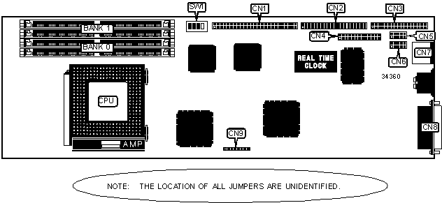
CONNECTIONS | |||
|
Purpose |
Location |
Purpose |
Location |
|
SCSI interface |
CN1 |
PS/2 mouse port |
CN7 |
|
IDE interface |
CN2 |
AUI connector |
CN8 |
|
Floppy drive interface |
CN3 |
AT keyboard connector |
CN9 |
|
Parallel port |
CN4 |
AUI receive LED |
JP4 |
|
Serial port 1 |
CN5 |
AUI active link LED |
JP5 |
|
Serial port 2 |
CN6 |
Hard drive LED |
JP7 |
|
USER CONFIGURABLE SETTINGS | |||
|
Function |
Label |
Position | |
|
» |
Parity select DPU generation |
JP2 |
Pins 1 & 2 closed |
|
Parity select CPU generation |
JP2 |
Pins 2 & 3 closed | |
|
» |
SCSI speed select 33MHz |
JP8 |
Pins 2 & 3 closed |
|
SCSI speed select 40MHz |
JP8 |
Pins 1 & 2 closed | |
|
» |
Watchdog timer enabled |
JP16 |
Pins 2 & 3 closed |
|
Watchdog timer disabled |
JP16 |
Pins 1 & 2 closed | |
|
» |
PS/2 IRQ 12 enabled |
JP17 |
Pins 1 & 2 closed |
|
Next Step OS used |
JP17 |
Pins 2 & 3 closed | |
|
» |
PCI bus speed select 33MHz |
JP23 |
Pins 2 & 3 closed |
|
PCI bus speed select 25MHz |
JP23 |
Pins 1 & 2 closed | |
|
» |
Factory configured - do not alter |
JP27 |
Unidentified |
|
» |
Monitor type select color |
SW1/1 |
On |
|
Monitor type select monochrome |
SW1/1 |
Off | |
|
» |
Flash BIOS enabled |
SW1/2 |
On |
|
Flash BIOS disabled |
SW1/2 |
Off | |
|
» |
CMOS memory normal operation |
SW1/3 |
Off |
|
CMOS memory clear |
SW1/3 |
On | |
|
» |
Factory configured - do not alter |
SW1/4 |
Unidentified |
|
DRAM CONFIGURATION | ||
|
Size |
Bank 0 |
Bank 1 |
|
8MB |
(2) 1M x 36 |
None |
|
16MB |
(2) 1M x 36 |
(2) 1M x 36 |
|
24MB |
(2) 2M x 36 |
(2) 1M x 36 |
|
32MB |
(2) 4M x 36 |
None |
|
40MB |
(2) 4M x 36 |
(2) 1M x 36 |
|
48MB |
(2) 4M x 36 |
(2) 2M x 36 |
|
64MB |
(2) 8M x 36 |
None |
|
64MB |
(2) 4M x 36 |
(2) 4M x 36 |
|
96MB |
(2) 8M x 36 |
(2) 4M x 36 |
|
128MB |
(2) 8M x 36 |
(2) 8M x 36 |
|
CACHE CONFIGURATION |
|
Note: The location of the cache is unidentified. |
|
CACHE JUMPER CONFIGURATION | ||
|
Size |
JP24 |
JP25 |
|
128KB |
Open |
Open |
|
256KB |
Closed |
Closed |
|
CPU TYPE SELECTION | ||||
|
Type |
JP1 |
JP14 |
JP15 |
JP18 |
|
80486SX |
Pins 2 & 3 closed |
Pins 2 & 3 closed |
Pins 2 & 3 closed |
Pins 1 & 2 closed |
|
80846DX |
Pins 2 & 3 closed |
Pins 2 & 3 closed |
Pins 2 & 3 closed |
Pins 2 & 3 closed |
|
80486DX2 |
Pins 1 & 2 closed |
Pins 2 & 3 closed |
Pins 2 & 3 closed |
Pins 2 & 3 closed |
|
80486DX4 |
Pins 1 & 2 closed |
Pins 2 & 3 closed |
Pins 2 & 3 closed |
Pins 2 & 3 closed |
|
P24D |
Pins 2 & 3 closed |
Pins 1 & 2 closed |
Pins 1 & 2 closed |
Pins 2 & 3 closed |
|
P24T |
Pins 2 & 3 closed |
Pins 1 & 2 closed |
Pins 1 & 2 closed |
Pins 2 & 3 closed |
|
CPU TYPE SELECTION | |
|
Type |
JP22 |
|
Non SL enhanced |
Pins 1 & 2 closed |
|
SL enhanced |
Pins 2 & 3 closed |
|
CPU CACHE SELECTION | ||||
|
CPU |
Cache |
JP6 |
JP12 |
JP19 |
|
80486SX |
WT/WT |
Pins 5 & 6 closed |
Pins 2 & 3 closed |
Closed |
|
80486SX |
WT/WB |
Pins 1 & 2 closed |
Pins 1 & 2 closed |
Open |
|
80846DX |
WT/WT |
Pins 5 & 6 closed |
Pins 2 & 3 closed |
Closed |
|
80846DX |
WT/WB |
Pins 1 & 2 closed |
Pins 1 & 2 closed |
Open |
|
80486DX2 |
WT/WT |
Pins 5 & 6 closed |
Pins 2 & 3 closed |
Closed |
|
80486DX2 |
WT/WB |
Pins 1 & 2 closed |
Pins 1 & 2 closed |
Open |
|
80486DX4 |
WT/WB |
Pins 5 & 6 closed |
Pins 2 & 3 closed |
Closed |
|
P24D |
WB/WT |
Pins 5 & 6 closed |
Pins 1 & 2 closed |
Closed |
|
CPU MULTIPLIER SELECTION | |
|
Multiplier |
JP13 |
|
2x |
Pins 2 & 3 closed |
|
3x |
Pins 1 & 2 closed |
|
SERIAL PORT 2 SELECTION | ||||
|
Setting |
JP9 |
JP10 |
JP11 | |
| » |
RS232 |
Pins 2 & 3 closed |
Pins 2 & 3 closed |
Pins 2 & 3 closed |
|
RS422 |
Pins 1 & 2 closed |
Pins 1 & 2 closed |
Pins 1 & 2 closed | |
|
RS485 |
Pins 1 & 2 closed |
Pins 1 & 2 closed |
Pins 1 & 2 closed | |