ALPHA MICROSYSTEMS
AM-190
|
Processor |
Motorola 68040 |
|
Processor Speed |
66MHz |
|
Chip Set |
Unidentified |
|
Video Chip Set |
None |
|
Maximum Onboard Memory |
128MB |
|
Maximum Video Memory |
None |
|
Cache |
128KB |
|
BIOS |
Unidentified |
|
Dimensions |
330mm x 218mm |
|
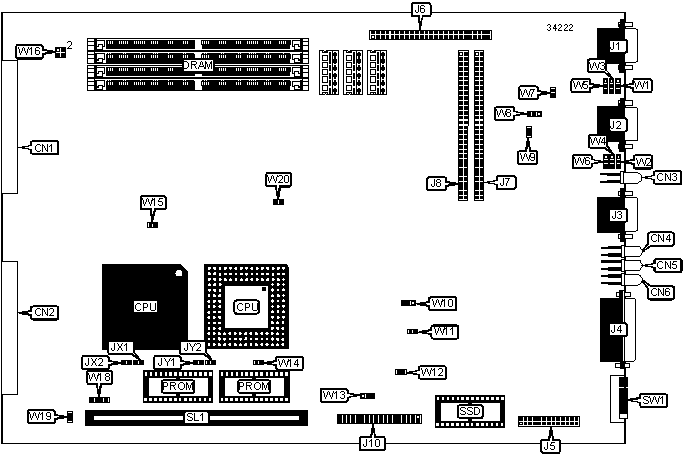
I/O Options |
Floppy drive interface, SCSI interface, serial ports (2), VME bus connectors (2), I/O bus connectors (2), UPS switch contact port, Ethernet LEDs (3), Memory configuration LED, AM-191 boot module slot, AUI port |
|
NPU Options |
None |
|
CONNECTIONS | |||
|
Purpose |
Location |
Purpose |
Location |
|
VME bus connector |
CN1 |
I/O bus connector |
J7 |
|
VME bus connector |
CN2 |
I/O bus connector |
J8 |
|
Serial port 1 |
J1 |
Floppy drive interface |
J10 |
|
Serial port 2 |
J2 |
+5v chassis fan power |
JX1 |
|
UPS switch contact port |
J3 |
+12v chassis fan power |
JX2 |
|
AUI port |
J4 |
+5v chassis fan power |
JY1 |
|
Front panel connector |
J5 |
+12v chassis fan power |
JY2 |
|
SCSI interface |
J6 |
AM-191 boot module slot |
SL1 |
|
USER CONFIGURABLE SETTINGS | |||
|
Function |
Label |
Position | |
|
» |
Remote reset disabled |
W7 |
Open |
|
Remote reset enabled |
W7 |
Closed | |
|
» |
Timeout clock source select 1MHz |
W8 |
Pins 2 & 3 closed |
|
Timeout clock source select 500KHz |
W8 |
Pins 1 & 2 closed | |
|
» |
Factory configured - do not alter |
W9 |
Closed |
|
» |
Factory configured - do not alter |
W11 |
Closed |
|
» |
Factory configured - do not alter |
W12 |
Closed |
|
» |
Ethernet sonic chip select 1/2 BCLK |
W13 |
Pins 1 & 2 closed |
|
Ethernet sonic chip select 1 BCLK |
W13 |
Pins 2 & 3 closed | |
|
» |
Factory configured - do not alter |
W15 |
Closed |
|
» |
MMU enabled |
W16/pins 1 & 2 |
Open |
|
MMU disabled |
W16/pins 1 & 2 |
Closed | |
|
» |
Factory configured - do not alter |
W18 |
Open |
|
» |
Factory configured - do not alter |
W19 |
Closed |
|
» |
80486 VPC disabled |
W20 |
Open |
|
80486 VPC enabled |
W20 |
Closed | |
|
DRAM CONFIGURATION | ||||
|
Size |
Bank 0 |
Bank 1 |
Bank 2 |
Bank 3 |
|
4MB |
(1) 1M x 36 |
None |
None |
None |
|
8MB |
(1) 1M x 36 |
(1) 1M x 36 |
None |
None |
|
12MB |
(1) 1M x 36 |
(1) 1M x 36 |
(1) 1M x 36 |
None |
|
16MB |
(1) 4M x 36 |
None |
None |
None |
|
16MB |
(1) 1M x 36 |
(1) 1M x 36 |
(1) 1M x 36 |
(1) 1M x 36 |
|
20MB |
(1) 4M x 36 |
(1) 1M x 36 |
None |
None |
|
24MB |
(1) 4M x 36 |
(1) 1M x 36 |
(1) 1M x 36 |
None |
|
28MB |
(1) 4M x 36 |
(1) 1M x 36 |
(1) 1M x 36 |
(1) 1M x 36 |
|
DRAM CONFIGURATION (CON'T) | ||||
|
Size |
Bank 0 |
Bank 1 |
Bank 2 |
Bank 3 |
|
32MB |
(1) 8M x 36 |
None |
None |
None |
|
32MB |
(1) 4M x 36 |
(1) 4M x 36 |
None |
None |
|
36MB |
(1) 8M x 36 |
(1) 1M x 36 |
None |
None |
|
40MB |
(1) 8M x 36 |
(1) 1M x 36 |
(1) 1M x 36 |
None |
|
44MB |
(1) 8M x 36 |
(1) 1M x 36 |
(1) 1M x 36 |
(1) 1M x 36 |
|
48MB |
(1) 8M x 36 |
(1) 4M x 36 |
None |
None |
|
48MB |
(1) 4M x 36 |
(1) 4M x 36 |
(1) 4M x 36 |
None |
|
64MB |
(1) 8M x 36 |
(1) 4M x 36 |
(1) 4M x 36 |
None |
|
64MB |
(1) 8M x 36 |
(1) 8M x 36 |
None |
None |
|
64MB |
(1) 4M x 36 |
(1) 4M x 36 |
(1) 4M x 36 |
(1) 4M x 36 |
|
80MB |
(1) 8M x 36 |
(1) 4M x 36 |
(1) 4M x 36 |
(1) 4M x 36 |
|
96MB |
(1) 8M x 36 |
(1) 8M x 36 |
(1) 8M x 36 |
None |
|
112MB |
(1) 8M x 36 |
(1) 8M x 36 |
(1) 8M x 36 |
(1) 4M x 36 |
|
128MB |
(1) 8M x 36 |
(1) 8M x 36 |
(1) 8M x 36 |
(1) 8M x 36 |
|
Note: The location of banks 0, 1, 2 & 3 are unidentified. Do not install SIMM in SL1. | ||||
|
CACHE CONFIGURATION |
|
Note: Board is factory installed with 128KB cache. The location is unidentified. |
|
CACHE JUMPER CONFIGURATION (80486 CACHE) | |
|
Setting |
W14 |
|
Enabled |
Closed |
|
Disabled |
Open |
|
CACHE JUMPER CONFIGURATION (68040 CACHE) | |
|
Setting |
W16/pins 3 & 4 |
|
Enabled |
Open |
|
Disabled |
Closed |
|
SERIAL PORT 1 SELECTION | ||||
|
Setting |
W1 |
W3 |
W5 | |
| » |
RS232 |
Pins 2 & 3 closed |
Pins 2 & 3 closed |
Pins 2 & 3 closed |
|
RS422 |
Pins 1 & 2 closed |
Pins 1 & 2 closed |
Pins 1 & 2 closed | |
|
SERIAL PORT 2 SELECTION | ||||
|
Setting |
W2 |
W4 |
W6 | |
| » |
RS232 |
Pins 2 & 3 closed |
Pins 2 & 3 closed |
Pins 2 & 3 closed |
|
RS422 |
Pins 1 & 2 closed |
Pins 1 & 2 closed |
Pins 1 & 2 closed | |
|
MAIN BOOT SELECTION | ||||
|
Setting |
SW1/5 |
SW1/6 |
SW1/7 |
SW1/8 |
|
Floppy |
Off |
Off |
Off |
Off |
|
SCSI disk drive |
Off |
Off |
Off |
On |
|
AM-520 |
Off |
On |
Off |
Off |
|
ALTERNATE BOOT SELECTION | ||||
|
Setting |
SW1/1 |
SW1/2 |
SW1/3 |
SW1/4 |
|
None |
Off |
Off |
Off |
Off |
|
Floppy |
Off |
Off |
Off |
On |
|
VCR |
Off |
Off |
On |
On |
|
SCSI streamer/DAT |
Off |
On |
On |
Off |
|
AM-640 MagTape |
Off |
On |
Off |
Off |
|
SCSI TERMINATION SELECTION | ||
|
Setting |
W10 | |
| » |
SCSI termination enabled |
Pins 2 & 3 closed |
|
SCSI termination disabled |
Pins 1 & 2 closed | |
|
DIAGNOSTIC LED(S) |
|
Note: Function of LEDs (CN3-CN6) are unidentified. |