AT & T, INC.
6300 XT
|
Processor |
8086 |
|
Processor Speed |
4.77MHz |
|
Chip Set |
None |
|
Max. Onboard DRAM |
640KB |
|
Cache |
None |
|
BIOS |
AT&T |
|
Dimensions |
272mm x 254mm |
|
I/O Options |
Parallel port, serial ports (2), floppy drive interface |
|
NPU Options |
8087 |
|
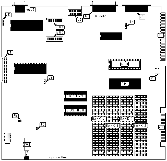
SYSTEM BOARD CONNECTIONS | |||
|
Purpose |
Location |
Purpose |
Location |
|
To CRT controller board at J9 |
J1 |
Serial port 2 |
J5 |
|
To CRT controller board at J11 |
J2 |
Keyboard |
J6 |
|
Serial port 1 |
J3 |
Floppy drive |
J7 |
|
Parallel port |
J4 |
+/- 12V Power |
P1 |
|
Note:Bus converter board and display enhancement board not shown. | |||
|
SYSTEM BOARD USER CONFIGURABLE SETTINGS | |||
|
Function |
Jumper/Switch |
Position | |
| » |
Factory configured - do not alter |
JA |
N/A |
| » |
Factory configured - do not alter |
JB |
N/A |
| » |
Clock enabled |
JC |
Closed |
|
Clock disabled |
JC |
Open | |
| » |
Factory configured - do not alter |
JD |
N/A |
| » |
Clock battery enabled |
JE |
Closed |
|
Clock battery disabled |
JE |
Open | |
| » |
NPU enabled |
SW0/5 |
Off |
|
NPU disabled |
SW0/5 |
On | |
| » |
Serial interface select 8250 |
SW0/6 |
On |
|
Serial interface select 8350 |
SW0/6 |
Off | |
| » |
BIOS type select 2732 |
SW0/8 |
On |
|
BIOS type select 2764 |
SW0/8 |
Off | |
| » |
Disk drive select 96 TPI |
SW1/1 |
Off |
|
Disk drive select 48 TPI |
SW1/1 |
On | |
| » |
Disk drive select fast start-up |
SW1/2 |
Off |
|
Disk drive select slow start-up |
SW1/2 |
On | |
|
DRAM CONFIGURATION | ||||
|
Size |
Bank 0 |
Bank 1 |
Bank 2 |
Bank 3 |
|
128KB |
(9) 4164 |
(9) 4164 |
NONE |
NONE |
|
256KB |
(9) 4164 |
(9) 4164 |
(9) 4164 |
(9) 4164 |
|
512KB |
(9) 4464 |
(9) 4464 |
NONE |
NONE |
|
640KB |
(9) 4164 |
(9) 4164 |
(9) 41256 |
(9) 41256 |
|
DRAM SWITCH CONFIGURATION | ||||
|
Size |
SW0/1 |
SW0/2 |
SW0/3 |
SW0/4 |
|
128KB |
Off |
On |
On |
On |
|
256KB |
On |
Off |
On |
On |
|
512KB |
On |
On |
Off |
On |
|
640KB |
Off |
On |
Off |
On |
|
VIDEO CONFIGURATION | ||
|
Size |
SW1/5 |
SW1/6 |
|
80 columns |
On |
Off |
|
40 columns |
Off |
On |
|
HARD DRIVE CONFIGURATION | ||
|
Setting |
SW1/3 |
SW1/4 |
|
Enabled |
Off |
Off |
|
Disabled |
On |
On |
|
FLOPPY DRIVE CONFIGURATION | ||
|
Drives installed |
SW1/7 |
SW1/8 |
|
1 |
On |
On |
|
2 |
Off |
On |
|
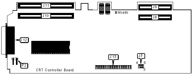
CRT CONTROLLER BOARD CONNECTIONS | |||
|
Purpose |
Location |
Purpose |
Location |
|
To bus converter board |
J8 |
Monitor |
J12 |
|
To system board at J1 |
J9 |
To display enhancement board |
J13 |
|
To bus converter board |
J10 |
+15V Power |
P2 |
|
To system board at J2 |
J11 | ||
|
CRT CONTROLLER BOARD USER CONFIGURABLE SETTINGS | |||
|
Function |
Jumper |
Position | |
| » |
Oscillator select internal |
JF |
pins 2 & 3 closed |
|
Oscillator select on display enhancement board |
JF |
pins 4 & 5 closed | |
| » |
Clock select internal |
JF |
pins 5 & 6 closed |
|
Oscillator select 24MHz |
JF |
pins 1 & 2 closed | |