INDUSTRIAL COMPUTER SOURCE
AD12-8
|
Card Type |
Analog to digital converter |
|
I/O Options |
parallel port |
|
Data Bus |
8-bit ISA |
|
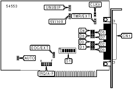
CONNECTIONS |
|
|
Function |
Label |
|
DB-37 connector |
CN1 |
|
USER CONFIGURABLE SETTINGS |
||
|
Function |
Label |
Position |
|
Sets Counter#1 output as Counter#2 clock input |
CLK0 |
closed |
|
Uses Counter#2 output to start preprogrammed A/D conversions |
TMR/EXT |
Pins 1 & 2 closed |
|
ANALOG INPUT RANGES |
||
|
Range |
10V/5V Jumper |
UNIP/BIP Jumper |
|
+/- 5V |
Pins 1 & 2 closed |
Pins 2 & 3 closed |
|
+/- 10V |
Pins 2 & 3 closed |
Pins 2 & 3 closed |
|
+ 10V |
Pins 1 & 2 closed |
Pins 1 & 2 closed |
|
INTERRUPT SOURCE SELECTION |
||
|
Function |
Label |
Position |
|
Selects interrupts caused by the end-of-conversion signal |
EXT/EOC |
Pins 1 & 2 closed |
|
Selects external interrupts |
EXT/EOC |
Pins 2 & 3 closed |
|
Note: The end-of-conversion interrupt is to be used only when the counter/timer or an external event are used to start A/D conversions. Use of the AUTO jumper or Software Start with the interrupts will degrade card speed. |
||
|
IRQ SELECTION |
||||||
|
Interrupt |
A |
B |
C |
D |
E |
F |
|
IRQ2 |
Closed |
Open |
Open |
Open |
Open |
Open |
|
IRQ3 |
Open |
Closed |
Open |
Open |
Open |
Open |
|
IRQ4 |
Open |
Open |
Closed |
Open |
Open |
Open |
|
IRQ5 |
Open |
Open |
Open |
Closed |
Open |
Open |
|
IRQ6 |
Open |
Open |
Open |
Open |
Closed |
Open |
|
IRQ7 |
Open |
Open |
Open |
Open |
Open |
Closed |
|
DIGITAL I/O CONFIGURATION |
||||||||
|
DIO |
D0 |
D1 |
D2 |
D3 |
D4 |
D5 |
D6 |
D7 |
|
DIO0 |
Closed |
Open |
Open |
Open |
Open |
Open |
Open |
Open |
|
DIO1 |
Open |
Closed |
Open |
Open |
Open |
Open |
Open |
Open |
|
DIO2 |
Open |
Open |
Closed |
Open |
Open |
Open |
Open |
Open |
|
DIO3 |
Open |
Open |
Open |
Closed |
Open |
Open |
Open |
Open |
|
DIO4 |
Open |
Open |
Open |
Open |
Closed |
Open |
Open |
Open |
|
DIO5 |
Open |
Open |
Open |
Open |
Open |
Closed |
Open |
Open |
|
DIO6 |
Open |
Open |
Open |
Open |
Open |
Open |
Closed |
Open |
|
DIO7 |
Open |
Open |
Open |
Open |
Open |
Open |
Open |
Closed |
|
BASE I/O ADDRESS SELECTION |
||||||||
|
Setting |
S1/7 |
S1/6 |
S1/5 |
S1/4 |
S1/3 |
S1/2 |
S1/1 |
|
|
|
000h |
On |
On |
On |
On |
On |
On |
On |
|
|
018h |
On |
On |
On |
On |
On |
Off |
Off |
|
|
038h |
On |
On |
On |
On |
Off |
Off |
Off |
|
|
078h |
On |
On |
On |
Off |
Off |
Off |
Off |
|
|
200h |
Off |
On |
On |
On |
On |
On |
On |
|
» |
300h |
Off |
Off |
On |
On |
On |
On |
On |
|
|
380h |
Off |
Off |
Off |
On |
On |
On |
On |
|
|
3C0h |
Off |
Off |
Off |
Off |
On |
On |
On |
|
|
3E0h |
Off |
Off |
Off |
Off |
Off |
On |
On |
|
|
3F0h |
Off |
Off |
Off |
Off |
Off |
Off |
On |
|
|
3F8h |
Off |
Off |
Off |
Off |
Off |
Off |
Off |
|
Note: A total of 128 base address settings are available. The switches are a binary representation of the decimal memory addresses. S1/7 is the Most Significant Bit and switch S1/1 is the Least Significant Bit. The switches have the following decimal values: S1/7=512, S1/6=256, S1/5=128, S1/4=64, S1/3=32, S1/2=16, S1/1=8. Turn off the switches and add the values of the switches to obtain the correct memory address. (Off=1, On=0) |
||||||||