ELITEGROUP COMPUTER SYSTEMS, INC.
DI-620
|
| |
|
Data bus: |
32-bit, VL-bus |
|
Size: |
Three/quarter-length, full-height card |
|
Hard drive supported: |
Four IDE (AT) Interface drives |
|
Floppy drives supported: |
Two 360KB, 720KB, 1.2MB, or 1.44MB drives |
|
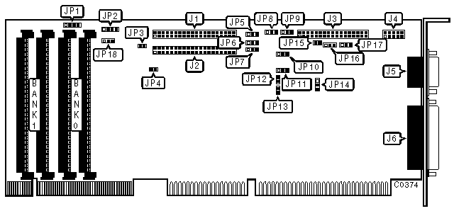
CONNECTIONS | |
|
Function |
Location |
|
40-pin IDE(AT) Interface connector (IDE-0) |
J1 |
|
40-pin IDE(AT) Interface connector (IDE-1) |
J2 |
|
34-pin control cable connector - floppy drive |
J3 |
|
10-pin serial port (COM2/4) - internal |
J4 |
|
10-pin serial port (COM1/3) - external |
J5 |
|
25-pin parallel port (LPT1/2) - external |
J6 |
|
4-pin connector - Diagnostic speaker |
JP1 |
|
4-pin connector - Drive active LED |
JP2 |
|
USER CONFIGURABLE SETTINGS | |||
|
Function |
Location |
Setting | |
|
IDE-0 (J1) read signal damping enabled |
JP3 |
open | |
|
IDE-0 (J1) read signal damping disabled |
JP3 |
closed | |
|
IDE-1 (J2) read signal damping enabled |
JP4 |
open | |
|
IDE-1 (J2) read signal damping disabled |
JP4 |
closed | |
| » |
Serial Port 1 (J5) enabled |
JP5, JP6 |
pins 1 & 2 closed |
|
Serial Port 1 (J5) disabled |
JP5, JP6 |
pins 2 & 3 closed | |
|
USER CONFIGURABLE SETTINGS | |||
|
Function |
Location |
Setting | |
| » |
Serial Port 2 (J4) enabled |
JP7, JP17 |
pins 1 & 2 closed |
|
Serial Port 2 (J4) disabled |
JP7, JP17 |
pins 2 & 3 closed | |
| » |
Parallel Port (J6) Interrupt is IRQ7 |
JP14 |
pins 2 & 3 closed |
|
Parallel Port (J6) Interrupt is IRQ5 |
JP14 |
pins 1 & 2 closed | |
| » |
CPU clock speed is 33 MHz or less |
JP18 |
pins 2 & 3 closed |
|
CPU clock speed is 50 MHz |
JP18 |
pins 1 & 2 closed | |
|
PARALLEL PORT (J6) CONFIGURATION | |||
|
LPT |
JP11 |
JP16 | |
| » |
LPT1 enabled |
pins 2 & 3 closed |
pins 1 & 2 closed |
|
LPT2 enabled |
pins 1 & 2 closed |
pins 1 & 2 closed | |
|
LPT3 enabled |
pins 1 & 2 closed |
pins 2 & 3 closed | |
|
Disabled |
pins 2 & 3 closed |
pins 2 & 3 closed | |
|
MISCELLANEOUS TECHNICAL NOTES |
|
J8, J9, and J15 are factory configured to JP8 - pins 2 & 3 closed, JP 9 - pins 1 & 2 closed, JP15 - open - do not alter these settings. The function of Jumpers JP10, JP12, and JP13 is not documented |